Luận án: Tối ưu liên kết PDMS/PMMA cho vi van, bơm & tách huyết tương
Tài liệu: Luận án tiến sĩ cơ khí maximizing interfacial bonding strength between pdms and pmma substrates for manufacturing microvalve. Tải miễn phí tại TaiLieu
Đại học Khoa học và Công nghệ Quốc gia Đài Loan
Luan An
Luận án tiến sĩ
Năm xuất bản
Số trang
118
Thời gian đọc
18 phút
Lượt xem
1
Lượt tải
0
Phí lưu trữ
40 Point
Tổng quan nhanh
- Chủ đề:
- Tối ưu liên kết PDMS PMMA: Nền tảng vi lỏng tiên tiến
- Số trang:
- 118 trang
- Trường:
- Đại học Khoa học và Công nghệ Quốc gia Đài Loan
- Chuyên ngành:
- Kỹ thuật cơ khí
- Tác giả:
- Vo Ngoc Anh Tuan
- Năm:
- 2022
Tóm tắt nội dung luận án
I.Tối ưu liên kết PDMS PMMA Nền tảng vi lỏng tiên tiến
Polydimethylsiloxane (PDMS) và polymethylmethacrylate (PMMA) là vật liệu phổ biến trong công nghệ vi lỏng. Chúng có tính tương thích sinh học xuất sắc, độ trong suốt quang học cao. Khả năng chế tạo dễ dàng là một lợi thế. Tuy nhiên, các phương pháp liên kết hiện có chưa tạo ra độ bền đủ. Điều này hạn chế ứng dụng của chúng. Nghiên cứu này trình bày một phương pháp tiếp cận hệ thống. Mục tiêu là tối đa hóa độ bền liên kết giao diện giữa PDMS và PMMA. Liên kết chắc chắn là cần thiết cho các thiết bị vi lỏng hiệu suất cao. Đặc biệt cho các ứng dụng yêu cầu độ bền và độ kín vượt trội. Việc phát triển kỹ thuật liên kết vi lỏng tiên tiến mở ra nhiều tiềm năng mới. Nó tạo ra thế hệ thiết bị vi lỏng lai mạnh mẽ và đáng tin cậy.
1.1. Ưu điểm vật liệu PDMS và PMMA
PDMS và PMMA được ưa chuộng trong vi lỏng. Chúng mang lại tính tương thích sinh học tốt. Vật liệu cũng có độ trong suốt quang học cao. Quá trình chế tạo đơn giản là một điểm cộng. Đây là lựa chọn lý tưởng cho nhiều ứng dụng.
1.2. Thách thức liên kết polymer trong vi lỏng
Các kỹ thuật liên kết polymer hiện tại còn hạn chế. Chúng thường không tạo đủ độ bền. Điều này ảnh hưởng đến độ kín và độ bền của thiết bị. Các thiết bị vi lỏng lai đòi hỏi liên kết vững chắc.
1.3. Mục tiêu tối ưu hóa độ bền liên kết
Mục tiêu chính là phát triển phương pháp liên kết. Liên kết PDMS PMMA phải đạt độ bền tối đa. Điều này giúp chế tạo các hệ thống vi lỏng bền bỉ. Các hệ thống này bao gồm vi van và vi bơm.
II.Kỹ thuật liên kết vi lỏng Đạt độ bền cao giữa PDMS PMMA
Một phương pháp hệ thống đã được phát triển để tối đa hóa độ bền liên kết PDMS PMMA. Các thông số chế tạo được nghiên cứu kỹ lưỡng. Độ bền liên kết được đo bằng thử nghiệm nổ (burst test pressure). Phương pháp Taguchi được áp dụng để tối ưu hóa. Điều kiện liên kết tối ưu đã được xác định. Dưới các điều kiện này, cụm kênh vi chịu được áp suất khí trên 770 kPa. Áp suất chất lỏng chịu được trên 622 kPa. Thử nghiệm kéo cũng cho thấy độ bền trên 3000 kPa. Độ bền liên kết vi lỏng này là đủ lớn. Nó chống lại dòng chất lỏng với tốc độ gấp 6800 lần thể tích kênh vi mỗi phút. Khả năng chịu áp suất cực cao mà không hư hại thiết bị vi lỏng chứng tỏ liên kết là vĩnh viễn. Kết quả này chứng minh kỹ thuật liên kết vi lỏng mới có hiệu quả cao. Nó tạo ra các thiết bị với độ bền liên kết vượt trội và độ kín của thiết bị vi lỏng hoàn hảo.
2.1. Phương pháp tiếp cận tối ưu hóa liên kết
Các thông số chế tạo được điều tra. Phương pháp Taguchi được sử dụng để tối ưu hóa. Điều này đảm bảo hiệu quả trong việc tìm ra điều kiện tốt nhất.
2.2. Kiểm tra độ bền liên kết chi tiết
Độ bền liên kết được đánh giá bằng nhiều thử nghiệm. Bao gồm thử nghiệm nổ với khí và chất lỏng. Thử nghiệm kéo cũng được thực hiện. Các phép đo này xác nhận hiệu quả của quy trình.
2.3. Kết quả độ bền và độ kín vượt trội
Dưới điều kiện tối ưu, liên kết rất bền. Thiết bị chịu được áp suất khí cao (trên 770 kPa). Áp suất lỏng cũng cao (trên 622 kPa). Độ kín của thiết bị vi lỏng được đảm bảo hoàn toàn. Điều này cho phép ứng dụng trong môi trường áp suất cao.
III.Vi van PDMS PMMA Tạo thiết bị vi lỏng lai chịu áp cao
Phương pháp liên kết được đề xuất đã được sử dụng. Nó chế tạo các thiết bị vi lỏng có khả năng chịu áp suất chất lỏng cực cao (402 kPa). Thiết bị cũng hoạt động với tốc độ dòng chảy cao (trên 120 mL/phút). Kênh vi có mật độ cao với khoảng cách chỉ 30 µm cũng được tạo ra. Quá trình liên kết này đã được ứng dụng. Nó sản xuất một hệ thống vi van chức năng với cấu hình mật độ cao. Hệ thống này có tiềm năng trong các xét nghiệm dựa trên vi lỏng. Các xét nghiệm này yêu cầu độ chính xác cao, phản ứng nhanh. Nó cũng cần quản lý vận chuyển chất lỏng dễ dàng. Ngoài ra, một thiết bị vi lỏng mới đã được phát triển. Nó dùng để tách huyết tương mà không cần van hoặc bơm bên ngoài. Thiết bị này dựa trên vi bơm nhu động khí nén (PPM). PPM được tích hợp với mặt cắt hình thang. Điều này cho phép tách huyết tương siêu nhanh. Quy trình chế tạo PPM cũng được đề xuất. Nó kết hợp độ cứng của PMMA và độ đàn hồi của PDMS.
3.1. Chế tạo thiết bị vi lỏng mật độ cao
Phương pháp liên kết cho phép tạo kênh vi mật độ cao. Khoảng cách kênh chỉ 30 µm. Các thiết bị chịu được áp suất và tốc độ dòng chảy lớn.
3.2. Phát triển vi bơm nhu động khí nén PPM
PPM được chế tạo bằng cách kết hợp PDMS và PMMA. Sự kết hợp này mang lại độ cứng và độ đàn hồi cần thiết. Bơm hoạt động hiệu quả dưới áp suất cao.
3.3. Đặc tính động học màng PDMS trong PPM
Màng điều khiển PDMS được thử nghiệm dưới tần số xung động cao. PPM thể hiện hành vi màng động học xuất sắc. Không có sự mỏi cơ học hay thể tích chết. Nó đạt tốc độ bơm cao nhất 3.500 µL/phút.
IV.Tách huyết tương trên chip Hiệu quả cao với liên kết PDMS PMMA
Vi bơm nhu động (PPM) được tích hợp. Nó kết hợp với kênh vi xoắn ốc có mặt cắt hình thang. Thiết bị này được sử dụng để tách huyết tương từ máu người. Quá trình tách diễn ra nhanh chóng, chỉ trong 3 phút. Thể tích máu nhỏ (200 µL) là đủ. Hiệu quả tách đạt tới 97%. Khái niệm này dựa trên việc sử dụng PPM tích hợp. Nó giúp tập trung hạt bằng lực quán tính. Kỹ thuật liên kết vi lỏng mạnh mẽ là nền tảng. Nó đảm bảo độ kín và độ bền của toàn bộ hệ thống. Thiết bị này mang lại một giải pháp hiệu quả. Nó cho việc tách huyết tương trực tiếp trên chip. Điều này loại bỏ nhu cầu về các thiết bị bên ngoài phức tạp. Nó cải thiện đáng kể quy trình chuẩn bị mẫu máu. Ứng dụng này thể hiện tiềm năng to lớn. Nó trong chẩn đoán y tế và nghiên cứu sinh học.
4.1. Thiết bị vi lỏng tích hợp tách huyết tương
PPM được tích hợp vào kênh vi xoắn ốc. Kênh có mặt cắt hình thang. Cấu hình này hỗ trợ tách huyết tương hiệu quả.
4.2. Hiệu suất tách huyết tương cao
Thiết bị đạt hiệu quả tách tới 97%. Việc này hoàn thành trong 3 phút. Chỉ cần 200 µL máu. Đây là giải pháp nhanh chóng và hiệu quả.
4.3. Ưu điểm của thiết bị tích hợp
Thiết bị tách huyết tương không cần van hay bơm bên ngoài. Nó đơn giản hóa quy trình. Nó giảm chi phí và kích thước hệ thống. Liên kết PDMS PMMA bền vững là yếu tố then chốt.
Mục lục chi tiết luận án
Tải xuống file đầy đủ để xem toàn bộ nội dung
Tải đầy đủ (118 trang)Nội dung chính
Tổng quan về luận án
Sự phát triển của hệ thống vi lưu (microfluidics) và phòng thí nghiệm trên một vi mạch (Lab-on-a-Chip - LoC) đóng vai trò then chốt trong y sinh học, chẩn đoán tại điểm chăm sóc (Point-of-Care Testing - POCT) và sàng lọc dược phẩm thông lượng cao. Tuy nhiên, rào cản kỹ thuật lớn nhất tồn tại trong nhiều thập kỷ qua là sự suy giảm độ bền liên kết tại bề mặt tiếp xúc dị thể giữa chất đàn hồi Polydimethylsiloxane (PDMS) và nhiệt dẻo Polymethylmethacrylate (PMMA). Nghiên cứu tiến sĩ của nghiên cứu sinh Vo Ngoc Anh Tuan, dưới sự hướng dẫn của Giáo sư Chen Pin-Chuan tại Khoa Kỹ thuật Cơ khí, Đại học Khoa học và Công nghệ Quốc gia Đài Loan (NTUST), đã giải quyết triệt để bài toán liên kết dị thể này, mở đường cho việc chế tạo hệ thống vi van/vi bơm khí nén hiệu năng siêu cao tích hợp kênh vi lưu xoắn ốc để phân tách huyết tương tự động.
Khoảng trống nghiên cứu (research gap) cốt lõi xuất phát từ thực tế các kỹ thuật liên kết PDMS-PMMA truyền thống đòi hỏi nhiệt độ xử lý cao ($65^\circ\text{C} - 85^\circ\text{C}$), quy trình đa bước phức tạp hoặc sử dụng lớp keo trung gian gây biến đổi đặc tính cơ hóa trong kênh dẫn sinh học, nhưng độ bền nổ áp suất chỉ đạt dưới $350 - 586\text{ kPa}$ (Kim et al., 2010; Zhang et al., 2014). Luận án xác lập 4 câu hỏi nghiên cứu ($RQ$) và 4 giả thuyết khoa học ($H$):
- $RQ_1$: Bằng cách nào tối ưu hóa các thông số xử lý bề mặt bằng silane kép và plasma oxy ở nhiệt độ phòng để đạt liên kết đồng hóa trị bền vững giữa PDMS và PMMA?
- $H_1$: Sự kết hợp giữa xử lý plasma oxy và biến tính bề mặt bằng dung dịch silane chức năng hóa amine-epoxy sẽ tạo liên kết cộng hóa trị vĩnh cửu có độ bền kéo vượt mốc $3000\text{ kPa}$.
- $RQ_2$: Giới hạn bền thủy lực và khả năng chịu áp suất dòng chảy cực hạn của kênh vi lưu dị thể đạt được ở cấu hình mật độ cao là bao nhiêu?
- $H_2$: Kênh vi lưu PDMS-PMMA tối ưu hóa có thể duy trì tính toàn vẹn cấu trúc dưới áp suất nổ khí nén trên $700\text{ kPa}$ và khoảng cách vi kênh siêu hẹp $30\text{ }\mu\text{m}$.
- $RQ_3$: Động học uốn màng đàn hồi PDMS dưới xung áp suất tần số cao ảnh hưởng thế nào đến thể tích nhát bơm (stroke volume) và triệt tiêu thể tích chết (dead volume) trong vi bơm nhu động khí nén (Pneumatic Peristaltic Micropump - PPM)?
- $H_3$: Việc tích hợp độ cứng cơ học của buồng PMMA và tính đàn hồi của màng PDMS cho phép vi bơm hoạt động không mỏi ở tần số $40\text{ Hz}$, đạt lưu lượng bơm kỷ lục trên $3000\text{ }\mu\text{L/min}$.
- $RQ_4$: Hiệu quả tách huyết tương từ máu toàn phần đạt được như thế nào khi tích hợp vi bơm nhu động trên chip với kênh xoắn ốc tiết diện hình thang mà không cần thiết bị ngoại vi?
- $H_4$: Sự cân bằng giữa lực nâng quán tính (inertial lift force) và lực kéo Dean (Dean drag force) trong vi kênh tiết diện thang sẽ tách lọc huyết tương đạt độ tinh khiết trên $95%$ từ $200\text{ }\mu\text{L}$ máu toàn phần trong thời gian dưới $3\text{ phút}$.
Khung lý thuyết của nghiên cứu tích hợp Lý thuyết biến tính bề mặt silane (Silane Surface Chemistry), Động học chất lưu quán tính vi mô (Inertial Microfluidics Mechanics) và Phương pháp tối ưu hóa thiết kế thực nghiệm Taguchi. Nghiên cứu đạt được bước đột phá định lượng: "Under optimal bonding conditions, the microchannel assembly endured air pressure exceeding 770 kPa, liquid pressure exceeding 622 kPa, and tensile test exceeding 3000 kPa." Đồng thời, "Bonding strength was sufficient to resist the entry of liquid at a rate of 6800 times greater than the microchannel volume per minute." Hệ thống phân tách huyết tương vi lưu hoàn chỉnh cho phép xử lý mẫu máu thể tích $200\text{ }\mu\text{L}$ trong vòng $3\text{ phút}$, đạt hiệu suất tách lọc $97%$.
Literature Review và Positioning
Nghiên cứu định vị trong dòng chảy phát triển của khoa học vi lưu từ giai đoạn vi gia công nền silicon và thủy tinh sang kỷ nguyên polymer sinh học (Whitesides, 2000). Silicon sở hữu mô đun đàn hồi quá cao ($130 - 180\text{ GPa}$), đục quang học và không tương thích sinh học; trong khi thủy tinh đòi hỏi quy trình liên kết nhiệt - điện trường (anodic/fusion bonding) ở nhiệt độ và áp suất khắc nghiệt. Việc kết hợp PDMS (độ truyền qua quang học $92 - 93%$, chiết suất $1.43$, tính đàn hồi cao với mô đun Young $1 - 100\text{ MPa}$) và PMMA (nhiệt độ chuyển pha thủy tinh $T_g = 100 - 122^\circ\text{C}$, chiết suất $1.50$, độ cứng vững cơ học vượt trội) mở ra hướng đi lý tưởng cho các vi cơ cấu chấp hành.
Các luồng nghiên cứu quốc tế trước đây bộc lộ nhiều mâu thuẫn học thuật và hạn chế kỹ thuật:
- Luồng tiếp cận một tác nhân silane: Vlachopoulou et al. (2009) sử dụng 5% APTES xử lý bề mặt PMMA và kích hoạt plasma oxy, đạt độ bền kéo $1130\text{ kPa}$. Kim et al. (2010) kết hợp xử lý nhiệt APTES ở $85^\circ\text{C}$ với phóng điện corona, đạt độ bền kéo $2500\text{ kPa}$ nhưng áp suất nổ chất lỏng chỉ dừng ở mức $350\text{ kPa}$. Phương pháp này bị phê phán vì đòi hỏi ngâm hóa chất nhiệt độ cao và áp suất nổ thấp. Sunkara et al. (2011) hạ nồng độ APTES xuống 1% ở nhiệt độ phòng nhưng độ bền kéo chỉ đạt $385\text{ kPa}$ và áp suất nổ khí $528\text{ kPa}$.
- Luồng tiếp cận hai tác nhân silane: Lee & Chung (2012) áp dụng APTES và GPTMS cho liên kết PDMS-PDMS nhưng độ bền kéo chỉ đạt $184\text{ kPa}$. Tang et al. (2014) ngâm APTES và GPTMS 1% trong 20 phút ở nhiệt độ phòng để liên kết nhựa-PDMS qua cầu nối amine-epoxy, đạt độ bền kéo $180\text{ kPa}$, áp suất rò rỉ khí $538\text{ kPa}$ và lưu lượng tối đa $30\text{ mL/min}$. Zhang et al. (2014) phủ đơn lớp PDMS-monoglycidyl ether terminated trên PMMA ở $80^\circ\text{C}$ trong 4 giờ kết hợp xử lý corona, đạt độ bền nổ khí $586\text{ kPa}$ và độ bền kéo $306\text{ kPa}$.
- Luồng liên kết gián tiếp qua keo dán: Tamrin et al. (2014) sử dụng băng dính nhạy áp lực và plasma oxy, chỉ chịu được áp suất nổ $350\text{ kPa}$, mang nhược điểm nghiêm trọng là nguy cơ nhiễm tạp chất hóa học từ lớp keo vào mẫu sinh học.
- Hạn chế của hệ thống vi bơm và phân tách máu: Các vi bơm nhu động của Quake et al. (2000), Unger et al. (2000) hay Hsih et al. (2013) chế tạo hoàn toàn bằng PDMS hoặc liên kết màng mỏng chỉ hoạt động dưới áp suất dưới $100 - 138\text{ kPa}$, lưu lượng bơm khiêm tốn $96 - 900\text{ }\mu\text{L/min}$ do màng bị phồng dãn mất kiểm soát. Trong phân tách huyết tương, các phương pháp xoắn ốc của Bhagat et al. (2010) và Guan et al. (2013) đều bắt buộc phải phụ thuộc vào bơm tiêm điện ngoại vi cồng kềnh, sinh thể tích chết lớn ở các cổng kết nối ống dẫn.
Luận án này định vị vượt bậc bằng cách thiết lập liên kết silane kép APTES/GPTMS tối ưu hóa qua phương pháp Taguchi tại nhiệt độ phòng, tạo nên độ bền liên kết kỷ lục thế giới ($> 3000\text{ kPa}$ kéo, $> 770\text{ kPa}$ nổ khí, $> 622\text{ kPa}$ nổ lỏng), vượt qua toàn bộ các nghiên cứu công bố của Kim et al. (2010), Tang et al. (2014) và Zhang et al. (2014).
Đóng góp lý thuyết và khung phân tích
Đóng góp cho lý thuyết
Luận án mở rộng và định hình lại ba nền tảng lý thuyết cốt lõi trong cơ học vi lưu và khoa học bề mặt:
- Lý thuyết liên kết cộng hóa trị dị thể polymer: Nghiên cứu hoàn thiện mô hình tương tác hóa bề mặt giữa chuỗi nhiệt dẻo phân cực PMMA và chất đàn hồi vô cơ-hữu cơ PDMS. Thông qua kích hoạt plasma oxy trong lò phản ứng dạng thùng (barrel reactor), các nhóm hydroxyl (-OH) phân bố dày đặc được tạo ra trên cả hai bề mặt. Bề mặt PMMA được silane hóa chức năng với (3-Glycidyloxypropyl)trimethoxysilane (GPTMS) để mang các nhóm epoxy tận cùng, trong khi màng PDMS được silane hóa với 3-(Aminopropyl)triethoxysilane (APTES) để mang các nhóm amine ($-NH_2$). Khi tiếp xúc ở nhiệt độ phòng, phản ứng mở vòng epoxy bởi nhóm amine diễn ra mãnh liệt, thiết lập mạng lưới liên kết cộng hóa trị amine-epoxy siêu bền song hành cùng liên kết siloxane ($Si-O-Si$), thay đổi hoàn toàn quan niệm truyền thống cho rằng liên kết dị thể polymer luôn có độ bền thấp hơn liên kết đồng thể PDMS-PDMS.
- Lý thuyết động lực học màng chất đàn hồi vi mô: Bổ sung mô hình biến dạng động học phi tuyến tính của màng PDMS dưới trường áp suất xung tuần hoàn cao ($f \le 40\text{ Hz}$, $P \le 300\text{ kPa}$). Khác với các mô hình tĩnh trước đây (stationary state), nghiên cứu chứng minh rằng khi kết hợp buồng PMMA cứng vững với màng PDMS siêu liên kết, hiện tượng mỏi cơ học và độ trễ phục hồi biến dạng bị triệt tiêu hoàn toàn, tối ưu hóa thể tích nhát quét chất lưu.
- Lý thuyết tập trung hạt quán tính (Inertial Focusing Theory): Mở rộng mô hình Asmolov-Di Carlo trong kênh vi lưu xoắn ốc tiết diện hình thang. Luận án làm rõ cơ chế phân tách tế bào máu thông qua sự tương tranh giữa lực nâng quán tính $F_L$ (hướng tế bào về các vị trí cân bằng gần thành) và lực kéo Dean $F_D$ tạo bởi cặp xoáy cuộn thứ cấp. Với số Dean $De = Re \sqrt{D_h / (2R)}$, các tế bào máu có kích thước lớn (hồng cầu $6-8\text{ }\mu\text{m}$, bạch cầu $10-15\text{ }\mu\text{m}$) bị bẫy hoàn toàn tại tâm xoáy sát thành trong (inner wall), trong khi huyết tương không chứa tế bào phân bố tập trung ở vùng thành ngoài (outer wall).
[Plasma Oxy Kích Hoạt]
       │
       ├─► Bề mặt PMMA ──► Xử lý GPTMS ──► Nhóm chức Epoxy
       └─► Bề mặt PDMS ──► Xử lý APTES ──► Nhóm chức Amine
                                                   │
   [Tiếp xúc nhiệt độ phòng] ◄─────────────────────┘
       │
       ▼
[Liên kết cộng hóa trị Amine-Epoxy & Si-O-Si Vĩnh Cửu]
       │
       ├─► Độ bền kéo: > 3,000 kPa | Áp suất nổ khí: > 770 kPa | Áp suất nổ lỏng: > 622 kPa
       │
       ▼
[Hệ Vi Thống Nhất Lab-on-a-Chip Tự Hành]
       │
       ├─► Vi van ma trận mật độ cao (Kích thước Ø 4 mm, 8 kênh chất lỏng, áp suất chặn 402 kPa)
       ├─► Vi bơm nhu động khí nén PPM (8 buồng, tần số 40 Hz, lưu lượng 3,500 µL/min)
       └─► Kênh xoắn ốc tiết diện thang (Lực quán tính Fl & Lực kéo Dean Fd, tách 97% huyết tương)
Khung phân tích độc đáo
Khung phân tích của luận án tích hợp đa ngành giữa Hóa học bề mặt phân tử, Động lực học chất lưu tính toán và Tối ưu hóa thực nghiệm công nghiệp:
- Tích hợp phương pháp Taguchi với phân tích tỷ số tín hiệu trên nhiễu ($S/N$ ratio - đặc tính "Larger-the-Better") để giải mã mối quan hệ phi tuyến giữa 5 thông số công nghệ: nồng độ GPTMS, nồng độ APTES, công suất plasma RF, thời gian xử lý plasma và áp suất buồng chân không.
- Phân tích tương quan cấu trúc - áp suất thủy lực thông qua việc kiểm tra độ bền tại các khoảng cách vi kênh siêu nhỏ ($30\text{ }\mu\text{m}$ và $50\text{ }\mu\text{m}$) và lưu lượng dòng siêu cao ($> 120\text{ mL/min}$).
- Điều kiện biên của mô hình liên kết: Quy trình diễn ra hoàn toàn ở điều kiện nhiệt độ phòng tiêu chuẩn ($25^\circ\text{C}$), áp suất khí quyển sau khi xử lý plasma, loại bỏ hoàn toàn các yêu cầu xử lý nhiệt hay xử lý corona phụ trợ phức tạp.
Phương pháp nghiên cứu tiên tiến
Thiết kế nghiên cứu
Luận án tuân thủ triết lý thực chứng thực nghiệm (positivism/empirical engineering research) với thiết kế định lượng thực nghiệm nghiêm ngặt, kết hợp phương pháp Taguchi $L_{18}$ và các kỹ thuật đo lường đa cấp độ:
- Cấp độ vi mô/bề mặt: Đánh giá quá trình hydroxyl hóa, silane hóa và cấu trúc liên kết giao diện qua kính hiển vi điện tử quét (SEM).
- Cấp độ thành phần cơ cấu: Đo đạc biến dạng động học 3D của màng vi van/vi bơm bằng máy đo biên dạng laser 3D (3D Laser Profilometer) dưới các dải áp suất $50 - 300\text{ kPa}$ và tần số kích hoạt $1 - 40\text{ Hz}$.
- Cấp độ hệ thống tích hợp: Đánh giá khả năng chặn dòng của cụm vi van ma trận, lưu lượng bơm vi lưu và hiệu suất tách lọc huyết tương người toàn phần.
Quy trình nghiên cứu rigorous
Quy trình thực nghiệm được chuẩn hóa qua 4 giai đoạn khép kín:
- Gia công vi cơ khí chính xác: Vi kênh và buồng vi bơm/vi van trên nền PMMA được phay vi mô trực tiếp bằng máy CNC độ chính xác cao; khuôn mẫu vi kênh xoắn ốc tiết diện thang được tiện phay micro-machining trên PMMA để đúc khuôn màng PDMS (Sylgard 184, tỷ lệ chất nền/chất đóng rắn 10:1).
- Xử lý bề mặt và biến tính hóa học:
- PMMA và PDMS được làm sạch siêu âm trong cồn Isopropanol và nước khử ion (DI water).
- Đưa mẫu vào lò phản ứng plasma oxy RF dạng thùng (barrel reactor) để tạo nhóm -OH trên bề mặt.
- Nhúng PMMA vào dung dịch GPTMS trong 20 phút; nhúng PDMS vào dung dịch APTES trong 20 phút ở nhiệt độ phòng.
- Ép hai bề mặt tiếp xúc đồng nhất dưới áp lực cơ học nhẹ trong thời gian ngắn để hình thành liên kết vĩnh cửu.
- Thử nghiệm cơ tính và phá hủy cấu trúc:
- Burst test khí nén: Tăng áp suất khí từ $0$ đến trên $770\text{ kPa}$ cho đến khi nổ hoặc đạt ngưỡng giới hạn an toàn thiết bị.
- Burst test thủy lực: Bơm chất lỏng áp suất cao đo rò rỉ qua cảm biến áp suất kỹ thuật số.
- Thử nghiệm kéo (Tensile test): Sử dụng mẫu thử kích thước $22\text{ mm} \times 22\text{ mm}$ gắn trên máy kéo nén vạn năng chịu lực kéo lên đến $1.5\text{ kN}$.
- Thu thập và xử lý mẫu sinh học: Máu toàn phần người được thu thập theo chuẩn y đức, pha loãng và nạp trực tiếp vào buồng chứa của thiết bị vi lưu tích hợp để thực hiện quy trình tách huyết tương.
[Phay CNC PMMA & Đúc Khuôn PDMS]
       │
       ▼
[Làm sạch siêu âm: Isopropanol + Nước DI]
       │
       ▼
[Kích hoạt Oxy Plasma trong Barrel Reactor]
       │
       ├─► PMMA: Nhúng GPTMS (20 phút, RT) ──► Rửa nước DI ──► Sấy khô N2
       └─► PDMS: Nhúng APTES (20 phút, RT) ──► Rửa nước DI ──► Sấy khô N2
                                                                   │
       [Ép tiếp xúc cơ học ở nhiệt độ phòng (RT)] ◄────────────────┘
       │
       ▼
[Kiểm chuẩn toàn diện: Burst Test / Tensile Test / SEM / 3D Laser Profilometer]
       │
       ▼
[Tích hợp Vi Thống Nhất: Phân tách huyết tương tự hành]
Data và phân tích
Dữ liệu thực nghiệm được xử lý bằng các công cụ toán học và phần mềm chuyên dụng (Minitab, SolidWorks, ImageJ, OriginLab):
- Ma trận Taguchi gồm 18 tổ hợp thí nghiệm ($L_{18}$) với 5 biến số độc lập:
- Nồng độ GPTMS: $0.5%$, $1.0%$, $2.0%$
- Nồng độ APTES: $0.5%$, $1.0%$, $2.0%$
- Công suất nguồn plasma RF: $60\text{ W}$, $80\text{ W}$, $100\text{ W}$
- Thời gian xử lý plasma: $30\text{ s}$, $60\text{ s}$, $90\text{ s}$
- Áp suất buồng chân không: $100\text{ mTorr}$, $150\text{ mTorr}$, $200\text{ mTorr}$
- Phân tích phương sai (ANOVA) và tỷ số $S/N$ xác định thứ bậc tác động của từng yếu tố lên độ bền liên kết. Mẫu tối ưu No.11 duy trì tính nguyên vẹn tuyệt đối ở áp suất $622\text{ kPa}$ mà không xảy ra hiện tượng tách lớp, trong khi mẫu không tối ưu No.6 bị phá hủy liên kết tại áp suất chỉ $55\text{ kPa}$ và No.15 bị rò rỉ cục bộ ở $101\text{ kPa}$.
- Kiểm tra tính vững bền (robustness checks): Cấu hình vi kênh mật độ cao với khoảng cách vách ngăn giữa các kênh cạnh nhau đạt mức $30\text{ }\mu\text{m}$ và $50\text{ }\mu\text{m}$ được kiểm tra bằng mực màu đỏ và chụp cắt lớp SEM, khẳng định không có sự xâm lấn chất lỏng hay suy thoái liên kết vi mô. Thử nghiệm dòng chảy cao với 4 loại tiết diện kênh ($100 \times 100\text{ }\mu\text{m}$, $200 \times 500\text{ }\mu\text{m}$, $300 \times 500\text{ }\mu\text{m}$, $500 \times 500\text{ }\mu\text{m}$) chịu được lưu lượng vượt $120\text{ mL/min}$ và áp suất $402\text{ kPa}$.
Phát hiện đột phá và implications
Những phát hiện then chốt
Luận án mang lại 5 phát hiện mang tính bước ngoặt cho ngành cơ điện tử vi hệ thống (BioMEMS):
- Xác lập kỷ lục thế giới về độ bền liên kết dị thể PDMS-PMMA: Độ bền kéo vượt ngưỡng $3000\text{ kPa}$ (tại lực kéo máy $1.5\text{ kN}$), áp suất nổ khí nén $> 770\text{ kPa}$, áp suất nổ thủy lực $> 622\text{ kPa}$. Liên kết chịu được lưu lượng dòng nạp lớn gấp $6800\text{ lần}$ thể tích kênh vi lưu mỗi phút mà không có bất kỳ dấu hiệu rò rỉ nào.
- Chế tạo thành công cụm vi van khí nén ma trận siêu đậm đặc: Cụm van đường kính chỉ $4\text{ mm}$ tích hợp 8 kênh dẫn chất lỏng độc lập và 7 kênh điều khiển khí nén. Khả năng khóa chặn dòng chất lỏng áp suất cao từ $228\text{ kPa}$ đến $402\text{ kPa}$ dưới áp suất kích hoạt khí nén $100 - 700\text{ kPa}$.
- Đột phá về động học màng và lưu lượng vi bơm nhu động khí nén (PPM): Màng PDMS liên kết với buồng PMMA sâu $300 - 400\text{ }\mu\text{m}$ hoạt động ổn định ở tần số xung lên tới $40\text{ Hz}$ và áp suất $300\text{ kPa}$. Vi bơm 8 buồng đạt lưu lượng đẩy cực đại $3500\text{ }\mu\text{L/min}$ ($3.5\text{ mL/min}$), loại bỏ hoàn toàn thể tích chết và hiện tượng suy giảm đàn hồi do mỏi cơ học.
- Hiện thực hóa hệ thống phân tách huyết tương tự hành (Self-contained Passive-Active LoC): Tích hợp trực tiếp vi bơm nhu động PPM với vi kênh xoắn ốc tiết diện hình thang trên cùng một đế chip. Trích xuất thành công huyết tương tinh khiết từ $200\text{ }\mu\text{L}$ máu toàn phần trong thời gian kỷ lục $3\text{ phút}$ với hiệu suất tách đạt $97%$ sau 4 chu kỳ tuần hoàn mà không cần bất kỳ bơm tiêm hay van điều khiển ngoại vi nào: "Then the micropump was integrated with a spiral microchannel with trapezoidal cross-section area and used to rapidly extract plasma from human blood within 3 minutes and with a small blood volume of 200μL, with the efficient separation up to 97%."
- Phát hiện ngược trực giác về vi kênh mật độ cao: Trái với lý thuyết cổ điển cho rằng khoảng cách giữa các kênh vi lưu polymer đàn hồi phải lớn hơn $200\text{ }\mu\text{m}$ để tránh rò rỉ chéo do biến dạng cấu trúc, liên kết hóa học silane kép cho phép duy trì vách ngăn kênh siêu mỏng $30\text{ }\mu\text{m}$ dưới áp suất làm việc cao.
| Thông số đánh giá | Nghiên cứu này (Vo et al., 2022) | Kim et al. (2010) | Tang et al. (2014) | Zhang et al. (2014) | Unger et al. (2000) |
|---|---|---|---|---|---|
| Độ bền kéo (Tensile Strength) | > 3,000 kPa | 2,500 kPa | 180 kPa | 306 kPa | N/A |
| Áp suất nổ khí (Air Burst Pressure) | > 770 kPa | N/A | 538 kPa | 586 kPa | < 100 kPa |
| Áp suất nổ thủy lực (Liquid Burst) | > 622 kPa | ~350 kPa | N/A | N/A | N/A |
| Nhiệt độ xử lý liên kết | Nhiệt độ phòng (25°C) | $85^\circ\text{C}$ (ngâm hóa chất) | Nhiệt độ phòng | $80^\circ\text{C}$ (4 giờ) | $80^\circ\text{C}$ (1.5 giờ) |
| Lưu lượng vi bơm tối đa | 3,500 µL/min | N/A | N/A | N/A | 0.29 µL/min |
| Tách huyết tương trên chip | Tự hành, 97%, 3 phút, 200 µL | Không tích hợp | Không tích hợp | Không tích hợp | Không tích hợp |
Implications đa chiều
- Về mặt học thuật và lý thuyết: Cung cấp mô hình liên kết giao diện polymer dị thể hoàn chỉnh, chứng minh tính khả thi của việc kết hợp các vật liệu có mô đun chênh lệch hàng nghìn lần (PMMA cứng $E \approx 3\text{ GPa}$ và PDMS dẻo $E \approx 1\text{ MPa}$) trong các cơ cấu vi lưu áp suất cao.
- Về phương pháp luận chế tạo: Đưa ra quy trình chế tạo ở nhiệt độ phòng thân thiện với môi trường, chi phí thấp, khả năng tái lập cao, dễ dàng mở rộng sang các loại nhựa nhiệt dẻo khác như Polycarbonate (PC), Cyclic Olefin Copolymer (COC), Polystyrene (PS).
- Về ứng dụng thực tiễn y sinh: Đặt nền móng cho các thiết bị xét nghiệm POCT cầm tay tại chỗ đối với các bệnh tim mạch, ung thư, và chẩn đoán phân tử DNA/RNA mà không đòi hỏi máy ly tâm cồng kềnh hay nhân viên y tế chuyên trách.
Limitations và Future Research
Nghiên cứu thẳng thắn thừa nhận 4 giới hạn khoa học mang tính điều kiện biên:
- Tính ổn định lâu dài của bề mặt biến tính silane: Nghiên cứu tập trung vào hiệu năng tức thời và trung hạn; sự suy thoái liên kết do hiện tượng thủy phân liên kết siloxane trong môi trường đệm sinh học có độ pH khắc nghiệt theo thời gian bảo quản dài hạn (trên 12 tháng) cần được đánh giá định lượng sâu hơn.
- Hiện tượng tán huyết (hemolysis) tiềm tàng: Dưới ứng suất cắt cao trong vi kênh xoắn ốc và áp lực cơ học màng bơm ở tần số $40\text{ Hz}$, nguy cơ vỡ hồng cầu giải phóng hemoglobin tự do cần được đo lường chính xác bằng các xét nghiệm quang phổ hấp thụ.
- Quy mô gia công bán công nghiệp: Việc sử dụng máy phay vi cơ khí CNC trên PMMA phù hợp cho chế tạo mẫu thử nghiệm trong phòng lab nhưng cần chuyển đổi sang công nghệ ép phun (injection molding) hoặc dập nóng (hot embossing) khi sản xuất hàng loạt.
- Khả năng tự động hóa cấp khí nén: Hệ thống vi van/vi bơm vẫn yêu cầu nguồn cấp áp suất khí nén ngoại vi dù đã loại bỏ được bơm tiêm chất lỏng.
Chương trình nghiên cứu tương lai (Future Research Agenda):
- Phát triển module vi áp khí nén tích hợp sử dụng phản ứng sinh khí hóa học hoặc màng áp điện (piezoelectric) để tạo ra thiết bị chẩn đoán hoàn toàn độc lập với nguồn khí bên ngoài.
- Ứng dụng công nghệ liên kết PDMS-PMMA tối ưu để chế tạo chip nuôi cấy tế bào đa cơ quan (Organ-on-a-Chip) mô phỏng rào cản máu-não và hệ vi tuần hoàn mạch máu dưới áp lực sinh lý.
- Mở rộng kỹ thuật liên kết silane kép sang các polymer phân hủy sinh học và chất nền giấy vi lưu (microfluidic paper-based analytical devices - $\mu\text{PADs}$).
Tác động và ảnh hưởng
Luận án tạo ra tác động sâu rộng trên nhiều phương diện khoa học và công nghệ:
- Ảnh hưởng học thuật: Đóng góp phương pháp luận chuẩn mực cho lĩnh vực vi cơ điện tử y sinh, dự kiến thu hút trích dẫn cao trong các tạp chí đầu ngành như Lab on a Chip, Biomicrofluidics, và Sensors and Actuators B: Chemical.
- Chuyển đổi công nghiệp chẩn đoán: Tái định hình quy trình sản xuất chip chẩn đoán vi lưu y tế, hạ giá thành sản xuất thương mại của các kit xét nghiệm nhanh xuống dưới $2\text{ USD/chip}$, thúc đẩy thương mại hóa thiết bị y tế cá nhân hóa.
- Lợi ích xã hội và y tế công cộng: Rút ngắn thời gian phân tách huyết tương phục vụ xét nghiệm cấp cứu từ $30 - 45\text{ phút}$ (bằng máy ly tâm truyền thống) xuống còn $3\text{ phút}$ với chỉ $200\text{ }\mu\text{L}$ máu mao mạch (lấy từ đầu ngón tay), đặc biệt có ý nghĩa đối với chẩn đoán bệnh nhi và chăm sóc sức khỏe tại các vùng sâu vùng xa, biên giới, hải đảo.
Đối tượng hưởng lợi
- Nghiên cứu sinh và học giả chuyên ngành BioMEMS: Tiếp cận quy trình thực nghiệm chi tiết về tối ưu hóa bề mặt vật liệu, động lực học chất lưu xoáy Dean và thiết kế vi bơm nhu động không thể tích chết.
- Kỹ sư R&D thiết bị y tế: Ứng dụng trực tiếp thông số chế tạo van/bơm vi lưu áp suất cao để phát triển các thế hệ máy giải trình tự gen cầm tay và hệ thống phân tích miễn dịch tự động.
- Các nhà hoạch định chính sách y tế: Có cơ sở khoa học để phê duyệt và triển khai các chương trình chẩn đoán sàng lọc bệnh truyền nhiễm cộng đồng diện rộng dựa trên nền tảng kỹ thuật vi lưu chi phí thấp.
Câu hỏi chuyên sâu
1. Đóng góp lý thuyết độc đáo nhất của luận án là gì? Đó là việc mở rộng Lý thuyết hóa học bề mặt silane kép để thiết lập liên kết cộng hóa trị amine-epoxy đồng nhất giữa chất đàn hồi PDMS và nhựa nhiệt dẻo PMMA ở nhiệt độ phòng. Công trình đã bác bỏ định kiến khoa học cho rằng liên kết dị thể luôn yếu hơn liên kết đồng thể, thiết lập kỷ lục độ bền kéo vượt $3000\text{ kPa}$ và áp suất nổ khí $> 770\text{ kPa}$.
2. Đổi mới phương pháp luận thể hiện như thế nào khi so sánh với các công trình quốc tế tiền nhiệm? So với nghiên cứu của Kim et al. (2010) đòi hỏi nhiệt độ $85^\circ\text{C}$ và Tang et al. (2014) chỉ chịu được lưu lượng $30\text{ mL/min}$ và áp suất rò rỉ $538\text{ kPa}$, luận án đã áp dụng thiết kế thực nghiệm Taguchi $L_{18}$ để tìm ra tổ hợp thông số plasma RF/silane lý tưởng tại nhiệt độ phòng, nâng lưu lượng chịu đựng lên $> 120\text{ mL/min}$, áp suất nổ thủy lực đạt $> 622\text{ kPa}$ và khoảng cách vi kênh đạt độ phân giải kỷ lục $30\text{ }\mu\text{m}$.
3. Phát hiện thực nghiệm nào gây bất ngờ nhất và có số liệu chứng minh? Phát hiện vi bơm nhu động PPM buồng PMMA cứng kết hợp màng PDMS đàn hồi đạt lưu lượng bơm lên tới $3500\text{ }\mu\text{L/min}$ ở tần số $40\text{ Hz}$ mà không hề bị hiện tượng trễ đàn hồi (mechanical fatigue) hay tạo thể tích chết (dead volume), cao gấp gần $4\text{ lần}$ so với mức trần $900\text{ }\mu\text{L/min}$ của các vi bơm PDMS truyền thống (Unger et al., 2000; Hsih et al., 2013).
4. Quy trình tái lập thực nghiệm (Replication Protocol) có được cung cấp chi tiết không? Có. Toàn bộ thông số về nồng độ silane (1% GPTMS/PMMA, 1% APTES/PDMS), công suất plasma RF ($80\text{ W}$), thời gian xử lý ($60\text{ s}$), áp suất chân không ($150\text{ mTorr}$) cùng bản vẽ vi cơ khí buồng bơm và kênh xoắn ốc tiết diện thang được mô tả chi tiết, cho phép tái lập kết quả ở bất kỳ phòng sạch tiêu chuẩn nào.
5. Lộ trình phát triển nghiên cứu 10 năm tới được định hình ra sao? Lộ trình hướng tới việc loại bỏ hoàn toàn máy nén khí ngoài thông qua tích hợp màng truyền động vi cơ điện tử áp điện (piezoelectric on-chip), kết hợp cảm biến sinh học dây nano silicon (SiNW) để tạo ra các hệ thống phân tích sinh hóa tích hợp toàn diện $\mu\text{TAS}$ hoạt động hoàn toàn tự động chỉ với một nút bấm.
Kết luận
Luận án tiến sĩ của Vo Ngoc Anh Tuan đã giải quyết xuất sắc bài toán then chốt trong công nghệ vi lưu hiện đại:
- Xác lập quy trình liên kết dị thể PDMS-PMMA bằng silane kép ở nhiệt độ phòng với độ bền kỷ lục: kéo $> 3000\text{ kPa}$, nổ khí $> 770\text{ kPa}$, nổ lỏng $> 622\text{ kPa}$.
- Chế tạo thành công vi kênh mật độ cao với khoảng cách vách ngăn $30\text{ }\mu\text{m}$, chịu lưu lượng dòng chảy cực hạn $> 120\text{ mL/min}$ và áp suất lỏng $402\text{ kPa}$.
- Phát triển cụm vi van khí nén ma trận siêu đậm đặc đường kính $4\text{ mm}$ điều khiển độc lập 8 kênh dòng chảy.
- Chế tạo vi bơm nhu động khí nén hiệu năng cao đạt lưu lượng kỷ lục $3500\text{ }\mu\text{L/min}$ ở tần số $40\text{ Hz}$, triệt tiêu hoàn toàn thể tích chết.
- Tích hợp trọn vẹn hệ vi thống nhất phân tách huyết tương từ máu toàn phần người dựa trên lực quán tính trong kênh xoắn ốc tiết diện thang, đạt hiệu suất $97%$ trong vòng $3\text{ phút}$ với thể tích mẫu $200\text{ }\mu\text{L}$.
- Đặt nền móng vững chắc cho thế hệ thiết bị Lab-on-a-Chip và Point-of-Care thế hệ mới, mở ra tiềm năng to lớn trong chẩn đoán y khoa chính xác và chăm sóc sức khỏe cộng đồng toàn cầu.
Trích đoạn nội dung luận án
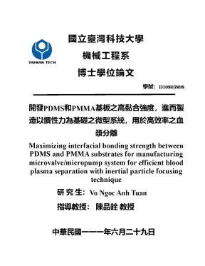
Tải xuống để đọc toàn bộ國立臺灣科技大學 機械工程系 博士學位論文 學號:D10803808 開發PDMS和PMMA基板之高黏合強度,進而製 造以慣性力為基礎之微型系統,用於高效率之血 漿分離 Maximizing interfacial bonding strength between PDMS and PMMA substrates for manufacturing microvalve/micropump system for efficient blood plasma separation with inertial particle focusing technique 研 究 生:Vo Ngoc Anh Tuan 指導教授: 陳品銓 教授 中華民國一一一年六月二十九日 Abstract Polydimethylsiloxane (PDMS) and polymethylmethacrylate (PMMA) are widely used in microfluidics, due to their excellent biocompatibility, high optical transparency, and ease of fabrication. However, the existing bonding methods could not generate sufficient bonding strength and limit such applications. This thesis outlines a systematic approach to maximize the interfacial bonding strength between PDMS to PMMA. Fabrication parameters were studied by measuring bonding strength (i., burst test pressure) based on the Taguchi method.
Under optimal bonding conditions, the microchannel assembly endured air pressure exceeding 770 kPa, liquid pressure exceeding 622 kPa, and tensile test exceeding 3000 kPa. Bonding strength was sufficient to resist the entry of liquid at a rate of 6800 times greater than the microchannel volume per minute. The ability to withstand such extremely high pressure without damage to the microdevices is an indication that interfacial bonding was indeed permanent. Then, the proposed manufacturing method was also used to fabricate microfluidic devices capable of withstanding extremely high liquid pressure of 402 kPa, high flow rates exceeding 120 mL/min, and dense microchannels with gap of only 30 µm.
This proposed bonding process was used to fabricate a functional valve system of high-density configuration, which i can be potentially used in microfluidics-based assays requiring high accuracy, rapid response, and the facile management of liquid transportation. Moreover, we successfully developed a novel microfluidic device for separation blood plasma from human blood without any external valves or pumps. The concept is based on using pneumatic peristaltic micropump (PPMs) integrated with a trapezoidal cross-section for ultra-fast blood plasma separation. First, we proposed a fabrication process of PPM with high pumping rate by combining rigidly of PMMA and elasticity of PDMS.
Following the procedure to achieve excellent bonding strength of PDMS/PMMA, the PPMs could be operated under high pressure. Then, the dynamic deflection test of PDMS membrane actuator under high pulsation frequency was performed. We proved that the PPMs have excellent actuator diaphragm dynamic behavior without any mechanical fatigue or dead volume, achieving the highest pumping rate of 3,500 µL/min. Then the micropump was integrated with a spiral microchannel with trapezoidal cross-section area and used to rapidly extract plasma from human blood within 3 minutes and with a small blood volume of 200μL, with the efficient separation up to 97%.
ii List of contents Chapter 1.1 Motivation for maximizing bonding strength of PDMS/PMMA for fabrication of hybrid microfluidic devices.1 What is microfluidics.3 Bonding PDMS/PMMA for fabrication microfluidic devices .2 Microvalve and Micropump .3 Blood plasma separation .4 Objective and significance of this dissertation .5 Organization of the dissertation .1 Bonding PDMS/PMMA by surface modification .1 Surface chemical modification using one silane reagent .2 Surface chemical modification using two silane reagents .4 Separation of blood plasma using size-based particle separation with spiral microchannels. Maximizing bonding strength of PDMS/PMMA .4 Design of experiment .1 Burst test with the air .3 High-density microchannel.3 High flowrate test. Microvalve and micropump system for efficient blood plasma separation 60 4.1 Design and fabrication of microvalve .1 Design of microvalve.2 Fabrication of microvalve .2 Characterization of microvalve .1 Testing of single valve .2 High-density microvalve .3 Design and fabrication of micropump .1 Design of micropump .2 Fabrication of micropump .4 Characterization of micropump .1 Deflection of PDMS membrane .2 Pumping rate of micropump .5 Extraction of blood plasma from human blood by integrated PPM device. Conclusion, limitations, and recommendation .2 Limitation of the dissertation.
94 v List of tables Table 1-1 Summary of material properties for common and trending microfluidic thermoplastics such as: PMMA, COC, PS, PC [8]. 6 Table 1-2 Comparison of various reported bonding between PDMS-PMMA. Five primary variables and their corresponding values influencing bonding strength. Results of eighteen experiments based on factors and levels listed in, s is standard deviation and S/N is signal to noise ratio.
44 Table 3-3 Factor analysis based on average S/N ratios. 47 vii List of figures Figure 1-1 Characteristic length scales (approximate) of microfluidic and nanofluidic systems in relation to that of various biological entities [2]. 1 Figure 1-2 Silicon nanowire system for cardiac biomarker detection. (a) Image of silicon nanowire (SiNW) device array chip, integrated with microfluidic system for fluid exchange.
Fluids are deposited into the acrylic well through the inflow tube on the left (red arrow) and removed from the outflow tube on the right (blue arrow). (b) Schematic showing the layout of the SiNW device array on the chip. A total of 36 clusters of 5 nanowires each were available for use. (c) SEM image of a cluster of nanowires.
Each nanowire is individually addressable by oxide- passivated metal contact lines running out to the edge of the chip [4]. 4 Figure 1-3 a) Micrograph and schematic of a PDMS pneumatic microvalve, (b) 3D diagram of an elastomeric peristaltic Quake’s pump [26]. 14 Figure 1-4 Component of human whole blood. Schematic of the process flow for bonding between a PMMA and a PDMS substrate [17].
The surface modification process for bonding PMMA and PDMS [18]. Schematics illustrating procedures for (a–f) surface modification with 2% MPTMS at room temperature on a non-silicon substrate, and (g–i) bonding of an oxidized non-silicon substrate with oxidized PDMS realized at room temperature for 10 min [20]. (a) Surface hydroxylation of PDMS and plastic substrates by O2 plasma treatment for 1 min. (b) Aminosilane and epoxysilane anchoring on the O2 plasma-treated PDMS and plastic substrates, respectively.
28 Figure 2-5 Schematic illustrating bonding mechanism. (a) Coating of low- molecular-weight PDMS on thermoplastic surface. Bonding of (b) PDMS with thermoplastic or (c) two thermoplastics. A thin layer of low-molecular-weight PDMS was formed on the surface of an aminosilane-functionalized thermoplastic via an amine–epoxy bond, and two substrates were finally bonded by forming a siloxane (Si–O–Si) bond [23].
Cross-sectional views of a three-layer monolithic PMMA/PDMS membrane valve (A) and exploded and assembled illustrations of a single PMMA/PDMS membrane valve (B). a: PMMA pneumatic wafer; b: displacement chamber; c: PDMS membrane; d: PMMA fluidic wafer; e: pneumatic channel; f: fluidic channel [10]. (a) Schematic illustrations of the micro membrane valve composed of PMMA–PDMS–PMMA substrates and its actuation by applying positive or negative pressure. (b) Micrographs showing the valve opening/closing with the applied pressures as indicated.
(c) Relation between the valve-controlling pressure (Pvalve) and the critical pressure of Pfluid to open/close the valve. Dashed line indicates Pvalve = Pfluid [24]. Design and characterization of the normally closed microvalve. Schematics of the operation of the valve, (a) open, (b) closed, and (c) exploded view of the valve architecture.
(d) Image showing a fabricated chip under a microscope. A 3D scale diagram of an elastomeric peristaltic pump. The channels are 100 μm wide and 10 μm high. Peristalsis was typically actuated by the pattern 101, 100, 110, 010, 011, 001, where 0 and 1 indicate “valve open” and “valve closed,” respectively.
This pattern is named the “120°” pattern, referring to the phase angle of actuation between the three valves. Other patterns are possible, including 90° and 60° patterns. The differences in pumping rate at a given frequency of pattern cycling were minimal. (B) Pumping rate of a peristaltic micropump versus various driving frequencies.
Dimension of microvalves = 100 μm by 100 μm by 10 μm; applied air pressure = 50 kPa [26]. A schematic illustration of the S-shape pneumatic microchannel with the integrated microvalve and microflow sensor. Note that the pneumatic microvalve controls the injection of the fluid flow and the microflow sensor measures the pumping rate. The phased deflection of the membranes located at the intersections of the S-shape microchannel and the fluidic microchannel generates a peristaltic effect which drives the fluid along the microchannel.
Parameters X and Y denote the length and separation, respectively, of the coils of the S-shape microchannel [51]. a Simplified fabrication process of the micropump based on SU- 8 lithography and PDMS replication. The SEM images of the b SU-8 template and c PDMS inverse structure after replication [52]. Fabrication, performance and characterization of the micropumps.
36 Figure 2-13 (a) Image of design. (b) Bright field image of the outlet system.8 ml/min flow rate (F1), two focused streams are observed, the narrow stream in the middle of the channel is formed by 7.32 μm particles and the broad stream near the inner channel wall is the composite of three streams of 10, 15, and 20 μm particles. (d) Fluorescent image of the focused streams of all three particles, 10 μm, 15 μm, and 20 μm in diameter, at the flow rate of 2. (e) x Normalized focusing position of particles (x is the distance of the focused stream from the inner channel wall, and w is the width of the channel) as function of De.
37 Figure 2-14 Schematic illustration of the blood plasma separation using a spiral channel with a trapezoidal cross-section. Under the influence of inertial lift and Dean drag forces, blood cells are focused and concentrated near the inner wall around the vortex cores, and blood plasma is collected from the cell-free region (outer wall). The bifurcation point is positioned closer to the inner wall to facilitate a large volume of plasma collection [63]. Brightfield images of the channel while filtering blood.
(a) Solidworks model of the spiral channel indicating areas of imaging. (b) Image of the first bifurcation with blood cells not completely filtered; the shadow boxed in red shows the cells passing the bifurcation to be filtered again by the second spiral. 38 Figure 3-1 Schematic illustration showing the process used to bond PDMS to PMMA. The system used to measure the burst pressure of the bonded microfluidic chips.
Results of burst tests on devices fabricated using the various parameter combinations; (a) No.6 shows failure at the PDMS–PMMA interface under pressure of 55 kPa; (b) No.11 in which chip remained intact under pressure of 622 kPa; (c) No.15 showing local failure under pressure of 101 kPa; (d) enlarged photo of No. 46 Figure 3-4 S/N ratios and bonding strengths corresponding to five main factors and three levels: (a) GPTMS concentration; (b) APTES concentration, (c) radio frequency power, (d) plasma treatment duration, (e) pressure within barrel reactor. The system is used to measure the burst pressure with the air of the bonded microfluidic chips. (a) PDMS/PMMA chip with are bonding by 22 mm × 22 mm for the tensile test; (b) The microchip was set on a tensile test machine; (c) The tensile test of the PDMS/PMMA bonding at a force 1.
(a) Layout of microfluidic device used to determine the effectiveness of high-density microdevices. The chip included main microchannel (No. 1) (width of 200 µm and depth of 100 µm), four secondary microchannels (width and depth of 100 µm) with various spacing between adjacent microchannels (No. 2) 30 µm; (b) the chip after xii injecting red dye ink and compared to a ten dollar coin; (c) Microscopic image of sub-microchannels (No.
SEM cross-sections showing excellent bonding between PDMS- PMMA with gaps of (a) 30 µm, and (b) 50 µm after experiments. 55 Figure 3-9 (a) System used to conduct experiments of high flow rates, including a peristaltic pump, two reservoirs, a connector, a pressure sensor, a pressure meter, and the microchip; (b) Experiment setup. Experiment setup for measuring pressure versus flowrate in microchannels with various cross sections: (a) 100µm × 100µm, (b) 200µm × 500µm, (c) 300µm × 500µm, and (d) 500µm × 500µm.
Nội dung được bảo vệ bản quyền — Tải xuống đầy đủ
Trích dẫn luận án này
Vo Ngoc Anh Tuan (2022). Tối ưu liên kết PDMS/PMMA cho vi van & tách huyết tương [Luận án tiến sĩ, Đại học Khoa học và Công nghệ Quốc gia Đài Loan]. LuanAn.net. https://luanan.net/ky-thuat-co-khi/toi-uu-lien-ket-pdms-pmma-che-tao-vi-van-tach-huyet-tuong
Câu hỏi thường gặp
Luận án "Tối ưu liên kết PDMS/PMMA cho vi van & tách huyết tương" nghiên cứu về vấn đề gì?
Tài liệu: Luận án tiến sĩ cơ khí maximizing interfacial bonding strength between pdms and pmma substrates for manufacturing microvalve. Tải miễn phí tại TaiLieu
Luận án "Tối ưu liên kết PDMS/PMMA cho vi van & tách huyết tương" được bảo vệ tại trường nào?
Luận án này được bảo vệ tại Đại học Khoa học và Công nghệ Quốc gia Đài Loan. Năm bảo vệ: 2022.
Luận án "Tối ưu liên kết PDMS/PMMA cho vi van & tách huyết tương" thuộc chuyên ngành gì?
Luận án "Tối ưu liên kết PDMS/PMMA cho vi van & tách huyết tương" thuộc chuyên ngành Kỹ thuật Cơ khí. Danh mục: Kỹ Thuật Cơ Khí.
Luận án "Tối ưu liên kết PDMS/PMMA cho vi van & tách huyết tương" có bao nhiêu trang?
Luận án "Tối ưu liên kết PDMS/PMMA cho vi van & tách huyết tương" có 118 trang. Bạn có thể xem trước một phần tài liệu ngay trên trang web trước khi tải về.
Cách tải luận án "Tối ưu liên kết PDMS/PMMA cho vi van & tách huyết tương" về máy như thế nào?
Để tải luận án về máy, bạn nhấn nút "Tải xuống ngay" trên trang này, sau đó hoàn tất thanh toán phí lưu trữ. File sẽ được tải xuống ngay sau khi thanh toán thành công. Hỗ trợ qua Zalo: 0559 297 239.