Luận án tiến sĩ: Tách CO2 H2S và mô hình WGS Membrane Reactor
Luận án tiến sĩ công nghệ tách CO2 và H2S bằng màng polymer. Mô hình WGS membrane reactor cho pin nhiên liệu đạt nồng độ CO2 >98% và khôi phục H2 >97%.
Luan An
Luận án Tiến sĩ
Năm xuất bản
Số trang
217
Thời gian đọc
33 phút
Lượt xem
1
Lượt tải
0
Phí lưu trữ
50 Point
Tổng quan nhanh
- Chủ đề:
- 1. CO2 H2S Membrane Separations Technology Overview
- Số trang:
- 217 trang
- Trường:
- The Ohio State University
- Chuyên ngành:
- Chemical Engineering
- Tác giả:
- Jin Huang
- Năm:
- 2007
Tóm tắt nội dung luận án
I. CO2 H2S Membrane Separations Technology Overview
Acid gas removal represents a critical challenge in environmental and energy processes. Traditional commercial technologies consume substantial energy and require significant infrastructure. Membrane-based CO2 and H2S capture offers transformative advantages. These systems demand less energy. Installation and operation remain simple. Process flexibility exceeds conventional methods. Weight and space requirements drop dramatically.
The technology faces limitations in large-scale applications. Transport properties remain relatively low compared to established methods. Recent advances in polymeric membranes address these constraints. Facilitated transport mechanisms enable breakthrough performance. CO2-selective membranes achieve permeability above 2000 Barrers. Selectivity ratios exceed 40 for CO2/H2 and 200 for CO2/N2 at operating temperatures of 100-150°C.
H2S removal demonstrates even superior characteristics. Higher reaction rates and smaller molecular size contribute to enhanced performance. H2S permeability surpasses CO2 values by threefold. H2S/H2 selectivity shows similar improvement ratios. These membrane separation technology advances enable practical deployment across multiple industries. Applications span from flue gas treatment to natural gas purification. The selective separation capability transforms acid gas removal economics.
1.1. Facilitated Transport Mechanism Benefits
Facilitated transport distinguishes advanced membranes from conventional barriers. Chemical carriers within the membrane matrix react reversibly with target gases. This mechanism accelerates transport while maintaining selectivity. Both CO2 and H2S exhibit facilitated effects in polymer membranes. The carrier-mediated process enhances membrane permeability substantially. Selectivity increases simultaneously through preferential chemical interaction.
1.2. Performance Metrics and Operating Conditions
Operating temperature ranges from 100 to 150°C for optimal performance. CO2 permeability exceeds 2000 Barrers under these conditions. CO2/H2 selectivity maintains values greater than 40. CO2/N2 selectivity surpasses 200 consistently. H2S demonstrates approximately triple the performance of CO2. These metrics position the technology competitively against established gas separation technology methods.
1.3. Comparative Advantages Over Traditional Methods
Energy consumption decreases significantly compared to amine scrubbing systems. Equipment footprint reduces by substantial margins. Installation complexity drops dramatically. Operational flexibility allows rapid response to process variations. Maintenance requirements remain minimal. Capital costs trend lower for moderate-scale applications. These advantages drive adoption in carbon capture and syngas purification applications.
II. CO2 Capture Applications in Industrial Processes
CO2 capture from flue gas and natural gas represents major industrial applications. Experimental results demonstrate exceptional separation performance. Using steam as sweep gas, permeate CO2 concentration exceeds 98% on dry basis. This purity level meets stringent requirements for carbon capture and sequestration. The membrane system processes gas mixtures containing N2 and H2 effectively.
Natural gas purification presents different challenges. Feed pressures reach 500 psia in typical operations. The membrane maintains decent CO2 transport properties under these elevated pressures. Methane recovery remains high while CO2 removal meets pipeline specifications. Thin-film composite membrane structures enhance performance dramatically. Selective layer thickness reduction increases CO2 flux proportionally. This architectural approach optimizes the balance between selectivity and productivity.
The ceramic membranes and polymer membranes each offer distinct advantages. Polymer systems excel in moderate temperature applications. Ceramic alternatives withstand higher temperatures and aggressive chemical environments. Material selection depends on specific process conditions. Both membrane types benefit from facilitated transport mechanisms. The technology scales effectively from laboratory to industrial installations. Economic viability improves with increasing production volumes.
2.1. Flue Gas CO2 Removal Performance
Flue gas applications target post-combustion carbon capture. Steam sweep gas enables high CO2 concentration in permeate stream. Dry basis purity exceeds 98% consistently. The system handles typical flue gas components including N2, O2, and water vapor. Membrane permeability remains stable across extended operating periods. Selective separation of CO2 from nitrogen proves highly effective.
2.2. Natural Gas Sweetening Operations
Natural gas contains CO2 and H2S as primary acid gas contaminants. Removal requirements vary based on pipeline specifications and end-use applications. The membrane system operates effectively at pressures up to 500 psia. CO2/CH4 separation maintains adequate selectivity under pressure. Transport properties remain acceptable across the operating pressure range. Acid gas removal meets commercial standards for natural gas quality.
2.3. Thin Film Composite Membrane Architecture
Composite membrane structure separates mechanical support from selective transport. Thin selective layers minimize mass transfer resistance. Support layers provide mechanical strength and chemical resistance. Decreasing selective layer thickness increases CO2 flux significantly. Optimization balances flux enhancement against selectivity maintenance. Manufacturing techniques enable precise thickness control in production.
III. Water Gas Shift Membrane Reactor Technology
CO2-selective water gas shift membrane reactors advance hydrogen production technology. The system combines catalytic reaction with membrane separation. Continuous CO2 removal shifts equilibrium forward. This approach enhances CO conversion beyond thermodynamic limitations. Hydrogen purity increases while operating temperatures decrease compared to conventional reactors.
Countercurrent flow configuration optimizes driving forces throughout the reactor. Feed gas enters opposite to sweep gas flow. This arrangement maintains concentration gradients along the reactor length. One-dimensional non-isothermal modeling predicts system performance accurately. Temperature profiles reflect exothermic reaction heat release and transport phenomena. The model accounts for simultaneous reaction and separation processes.
Performance targets challenge conventional WGS technology. CO concentration below 10 ppm becomes achievable from reforming syngases. Hydrogen recovery exceeds 97% in optimized configurations. These metrics satisfy fuel cell feed requirements directly. The water gas shift reaction proceeds efficiently at moderate temperatures. Process pressure maintenance eliminates compression energy penalties. Syngas purification occurs in a single integrated unit operation.
3.1. Equilibrium Shift Through CO2 Removal
Reversible WGS reaction faces equilibrium limitations in conventional reactors. Continuous CO2 removal drives reaction forward beyond equilibrium conversion. Le Chatelier's principle explains this enhancement mechanism. Product removal reduces CO concentration to parts-per-million levels. The membrane provides selective CO2 permeation while retaining hydrogen. Reaction proceeds continuously as CO2 exits the system.
3.2. Countercurrent Reactor Configuration Benefits
Countercurrent flow maximizes concentration driving forces. Feed gas contacts sweep gas with lowest CO2 content. Permeate exit contacts feed with highest CO2 concentration. This arrangement optimizes membrane utilization efficiency. Temperature profiles develop naturally from reaction exotherm and heat transfer. The configuration enables compact reactor design with high performance.
3.3. Modeling and Experimental Validation
One-dimensional non-isothermal model captures essential physics. Reaction kinetics, mass transfer, and heat transfer couple in the simulation. Model predictions agree well with experimental measurements. CO concentration drops below 10 ppm as predicted. Hydrogen recovery matches modeling results closely. The validated model enables scale-up design and optimization studies.
IV. Hydrogen Production for Fuel Cell Applications
Fuel cell systems demand ultra-pure hydrogen with minimal CO content. Even trace CO levels poison fuel cell catalysts. Traditional hydrogen production requires multiple purification steps. WGS membrane reactors integrate reaction and purification in single equipment. This integration reduces capital costs and operational complexity. Process intensification improves overall system efficiency.
Reforming syngases contain CO, CO2, H2, and water vapor. The membrane reactor processes this mixture directly. CO oxidation through water gas shift reaction produces additional hydrogen. Simultaneous CO2 removal prevents reverse reaction. The permeate stream carries concentrated CO2 for capture or utilization. Retentate stream contains purified hydrogen at process pressure.
Hydrogen production efficiency impacts fuel cell system economics significantly. Recovery rates above 97% minimize hydrogen losses. CO levels below 10 ppm eliminate downstream purification requirements. The membrane reactor operates at moderate temperatures between 100-150°C. This temperature range suits integration with fuel processors. Energy efficiency exceeds conventional multi-step purification trains. The technology enables compact, efficient fuel cell hydrogen processing systems.
4.1. Fuel Cell Hydrogen Purity Requirements
Proton exchange membrane fuel cells tolerate minimal CO contamination. CO concentrations must remain below 10-50 ppm depending on cell design. Higher CO levels adsorb on platinum catalysts irreversibly. Cell performance degrades rapidly with catalyst poisoning. Hydrogen purity specifications typically exceed 99.95%. The membrane reactor meets these stringent requirements directly without additional purification.
4.2. Integration with Fuel Processing Systems
Fuel processors convert hydrocarbon fuels to hydrogen-rich gas. Steam reforming or partial oxidation produces syngas. The membrane reactor follows reforming operations directly. Operating temperature compatibility enables thermal integration. Heat recovery between process streams improves efficiency. The integrated system reduces equipment count and footprint substantially.
4.3. Process Efficiency and Economic Advantages
Single-step purification eliminates multiple separation units. Capital costs decrease compared to conventional approaches. Operating costs benefit from reduced energy consumption. Hydrogen recovery above 97% minimizes fuel waste. Process pressure maintenance avoids compression energy penalties. Economic analysis favors membrane reactor technology for distributed hydrogen production applications.
V. Membrane Material Science and Performance
Polymeric membranes dominate moderate temperature gas separation applications. Material selection balances permeability, selectivity, and stability. Facilitated transport membranes incorporate chemical carriers within polymer matrices. These carriers react reversibly with target gas molecules. The reaction-diffusion mechanism enhances both transport rate and selectivity.
Polymer membrane composition determines performance characteristics. Hydrophilic polymers support aqueous carrier solutions. Carrier concentration affects both permeability and selectivity. Optimization requires balancing multiple competing factors. Membrane thickness inversely affects flux while supporting mechanical integrity. Composite structures separate these functions into distinct layers.
Ceramic membranes offer advantages for high-temperature applications. Thermal stability exceeds polymer capabilities significantly. Chemical resistance withstands aggressive process environments. Manufacturing costs remain higher than polymer alternatives. Membrane permeability typically runs lower than facilitated transport polymers. Application selection depends on specific process requirements. Both material classes contribute to advancing gas separation technology across diverse applications.
5.1. Facilitated Transport Carrier Chemistry
Chemical carriers enable selective gas transport through reversible reactions. Carbonate and bicarbonate systems facilitate CO2 transport effectively. Amine-based carriers show high reactivity with acid gases. Carrier mobility within polymer matrix affects overall permeability. Reaction kinetics must exceed diffusion rates for facilitation. Carrier concentration optimization balances performance against physical properties.
5.2. Polymer Matrix Selection Criteria
Polymer selection considers chemical compatibility with carriers and process gases. Hydrophilic polymers accommodate aqueous carrier solutions. Glass transition temperature affects operating temperature range. Mechanical properties ensure membrane integrity under pressure differentials. Chemical stability prevents degradation during extended operation. Commercial availability and cost influence practical implementation decisions.
5.3. Ceramic Membrane Characteristics
Ceramic membranes withstand temperatures exceeding 500°C routinely. Chemical inertness provides stability in corrosive environments. Pore size distribution determines separation selectivity mechanisms. Surface modification enhances selective transport properties. Manufacturing complexity increases production costs. Applications justify premium costs through superior durability and performance under extreme conditions.
VI. Future Developments in Membrane Separation
Membrane separation technology continues advancing through materials innovation and process optimization. Emerging polymer chemistries promise enhanced performance characteristics. Nanocomposite membranes incorporate inorganic fillers for property enhancement. Mixed matrix membranes combine polymer and ceramic advantages. These hybrid approaches target performance gaps in current technologies.
Manufacturing scale-up remains critical for commercial deployment. Thin-film composite production requires precise process control. Defect-free selective layers determine actual separation performance. Quality assurance protocols ensure consistent membrane properties. Cost reduction through manufacturing optimization enables broader market penetration. Automation and continuous production methods improve economics substantially.
Application expansion drives technology development priorities. Carbon capture from power generation represents massive potential markets. Biogas upgrading offers distributed renewable energy applications. Hydrogen production supports emerging fuel cell and chemical industries. Syngas purification enables cleaner chemical synthesis routes. Each application presents unique technical and economic requirements. Membrane technology flexibility allows customization for specific process conditions. Continued research and development will expand capabilities and reduce costs across all application areas.
6.1. Advanced Membrane Materials Development
Nanocomposite membranes incorporate nanoparticles into polymer matrices. These additives enhance mechanical properties and thermal stability. Selective transport can improve through preferential pathway creation. Mixed matrix membranes combine polymer processability with ceramic performance. Research focuses on optimizing filler loading and dispersion. Novel polymer chemistries target higher intrinsic permeability and selectivity.
6.2. Manufacturing and Scale Up Challenges
Large-scale production requires reproducible coating processes. Defect density must remain minimal for commercial viability. Automated inspection systems detect membrane imperfections. Process control ensures consistent selective layer thickness. Module fabrication techniques affect overall system performance. Cost reduction through manufacturing improvements remains a primary objective.
6.3. Emerging Application Opportunities
Post-combustion carbon capture addresses climate change mitigation. Biogas upgrading converts waste to pipeline-quality renewable natural gas. Hydrogen production supports clean energy transition strategies. Syngas purification enables sustainable chemical manufacturing. Each application requires optimized membrane properties and system configurations. Market growth drives continued technology investment and innovation.
Mục lục chi tiết luận án
Tải xuống file đầy đủ để xem toàn bộ nội dung
Tải đầy đủ (217 trang)Nội dung chính
Tổng quan về luận án
Công nghệ tách khí bằng màng polymer đóng vai trò chiến lược trong việc giải quyết thách thức kép: thu giữ khí nhà kính (CO2) và tinh chế nhiên liệu sạch (H2) phục vụ pin nhiên liệu (fuel cells). Nghiên cứu của tác giả Jin Huang (2007) dưới sự hướng dẫn của Giáo sư W. Winston Ho tại Đại học Bang Ohio (The Ohio State University, Khoa Kỹ thuật Hóa học) đã tạo ra bước đột phá trong việc khắc phục giới hạn đánh đổi (trade-off) giữa độ thấm (permeability) và độ chọn lọc (selectivity) vốn tồn tại dai dẳng trên các màng polymer truyền thống tuân theo cơ chế hòa tan - khuếch tán thuần túy (Robeson, 1991).
Khoảng trống nghiên cứu (research gap) trọng tâm nằm ở việc các màng polymer thông thường (như polyimide, polysulfone, cellulose acetate) có độ thấm CO2 rất thấp và không thể tách hiệu quả CO2 khỏi H2 do kích thước động học phân tử của H2 (2,89 Å) nhỏ hơn CO2 (3,30 Å). Đồng thời, sự hiện diện của khí độc H2S dù ở nồng độ vết (> 10 ppb) cũng làm vô hiệu hóa xúc tác anode của pin nhiên liệu. Nghiên cứu giải quyết 4 câu hỏi và giả thuyết khoa học cốt lõi:
- Giả thuyết H1: Việc tích hợp đồng thời chất mang cố định (fixed carrier - polyallylamine) và chất mang linh động (mobile carrier - muối kali 2-aminoisobutyric acid / AIBA-K) vào mạng lưới polymer ưa nước poly(vinyl alcohol) (PVA) khâu mạch sẽ tạo ra cơ chế vận chuyển tạo thuận kép (dual facilitated transport), cho phép vượt qua giới hạn Robeson upper bound.
- Giả thuyết H2: Khí mang tính axit mạnh hơn như H2S sẽ có tốc độ phản ứng trao đổi proton nhanh hơn và ion sản phẩm kích thước nhỏ hơn (HS-), dẫn đến độ thấm và độ chọn lọc vượt trội hơn so với CO2.
- Giả thuyết H3: Cấu trúc màng composite màng mỏng (TFC) với lớp chọn lọc siêu mỏng trên nền xốp polysulfone/PTFE sẽ giải phóng hoàn toàn trở lực truyền khối, tăng thông lượng thấm ở dải áp suất cao (lên đến 500 psia).
- Giả thuyết H4: Tích hợp màng chọn lọc CO2 vào lò phản ứng chuyển dịch nước - khí (Water-Gas-Shift - WGS) dạng sợi rỗng (hollow fiber) vận hành ngược chiều (countercurrent) sẽ phá vỡ cân bằng nhiệt động học Le Chatelier, hạ nồng độ CO xuống dưới 10 ppm và nâng độ thu hồi H2 lên trên 97%.
Về mặt định lượng, công trình đạt được những thông số thực nghiệm vượt bậc: độ thấm CO2 đạt 6.196 Barrers tại 110°C, duy trì trên 2.000 Barrers tại 100–150°C; độ chọn lọc CO2/H2 > 40 (đạt đỉnh 270 tại 110°C); độ chọn lọc CO2/N2 > 200 (đạt đỉnh 493); độ thu hồi H2S từ 50 ppm xuống < 100 ppb ở tốc độ không gian GHSV ~ 5.800 hr⁻¹; và nồng độ CO dòng ra của lò phản ứng WGS giảm xuống dưới 10 ppm, đáp ứng hoàn hảo tiêu chuẩn khắt khe của màng điện phân polymer (PEMFC).
Literature Review và Positioning
Lịch sử phát triển của màng tách khí ghi nhận các mốc tiến hóa quan trọng từ cơ chế thẩm thấu cổ điển của Fick và Graham thế kỷ 19, bước ngoặt màng bất đối xứng qua quá trình đảo pha của Loeb và Sourirajan (1962, 1964), đến công nghệ phủ màng composite của Ward et al. (1976) và Henis & Tripodi (1980) mở đường cho hệ thống thương mại PRISM®. Tuy nhiên, trong lĩnh vực loại bỏ khí axit, các công nghệ hấp thụ hóa học truyền thống bằng dung dịch alkanolamine (MEA, DEA, MDEA) (Kohl & Riesenfeld, 1979) hoặc hấp thụ vật lý (Rectisol®, Selexol®) đòi hỏi tháp cồng kềnh, chi phí tái sinh nhiệt khổng lồ và tiêu hao nhiều năng lượng nén lại dòng khí.
Trong y văn màng vận chuyển tạo thuận (Facilitated Transport Membrane - FTM), tồn tại hai trường phái đối lập rõ rệt:
- Trường phái màng chất lỏng cố định (Immobilized Liquid Membranes - ILM) do Sirkar và cộng sự (Chen et al., 2000; Kovvali & Sirkar, 2001) đại diện: Sử dụng dung môi amine hoặc muối carbonate cố định trong chất nền vi xốp (PVDF, Celgard). Ưu điểm là độ khuếch tán phản ứng cao, nhưng nhược điểm chí mạng là chất mang dễ bị rửa trôi (washout) và màng bị khô kiệt (dry-out) khi vận hành trên 80°C hoặc chênh áp cao.
- Trường phái màng chất mang cố định (Fixed Carrier Membranes) do Cussler et al. (1989), Noble (1990), và Matsuyama et al. (1994, 1999) phát triển: Gắn amine trực tiếp vào mạch polymer bằng phản ứng ghép nhánh plasma hoặc tổng hợp copolymer (như polyethylenimine, polyvinylamine). Dù độ bền cơ nhiệt cao nhưng thông lượng thấm thường thấp do chất mang bị giới hạn chuyển động dọc theo mạch polymer (chế độ chuyền vị trí "Tarzan swing").
Nghiên cứu của tác giả định vị chính xác vào điểm giao thoa: phát triển hệ màng hydrogel polymer ưa nước PVA khâu mạch acetal hóa bằng formaldehyde, phối trộn đồng thời polyallylamine (chất mang cố định) và muối kali của axit amin bị cản trở không gian (AIBA-K - chất mang linh động). Khi so sánh với các nghiên cứu quốc tế cùng thời kỳ như màng polyvinylamine khâu mạch của Kim et al. (2004) (độ truyền qua 0,014 m³(STP)/m²·bar·h, CO2/CH4 > 1.000 ở áp suất 1–4 bar) hay màng vô cơ sol-gel gắn amine của Xomeritakis et al. (2005), màng polymer composite của Jin Huang chứng minh sự vượt trội toàn diện về khả năng chịu nhiệt (100–150°C), chịu áp suất cao (500 psia) và duy trì độ chọn lọc CO2/H2 cực cao trong điều kiện thực tế của khí cải hóa tự nhiệt.
Đóng góp lý thuyết và khung phân tích
Đóng góp cho lý thuyết
Luận án mở rộng và hợp nhất ba nền tảng lý thuyết phản ứng - truyền khối kinh điển:
- Mở rộng lý thuyết tương tác Amin - Khí axit: Vận dụng cơ chế Zwitterion (Caplow, 1968; Danckwerts, 1979) kết hợp hiệu ứng cản trở không gian (steric hindrance) của Sartori & Savage (1983). Bằng việc sử dụng AIBA-K, nhóm amino liên kết với carbon bậc bốn làm giảm hằng số bền carbamate ($K_c$), thúc đẩy phản ứng thủy phân tạo ion bicarbonate ($HCO_3^-$), nâng tải trọng hấp thụ lý thuyết từ 0,5 mol CO2/mol amine lên 1,0 mol CO2/mol amine theo phương trình: $$CO_2 + RNH_2 + H_2O \rightleftharpoons RNH_3^+ + HCO_3^-$$
- Lý thuyết vận chuyển "Tarzan swing" và Percolation: Bổ sung cơ chế chất mang lai (hybrid carrier matrix). Khí CO2 và H2S không chỉ chuyền qua các nút amine cố định trên mạch polyallylamine theo lý thuyết ngưỡng thấm của Cussler et al. (1989) và Noble (1990), mà còn được vận chuyển song song bởi các ion AIBA-K và $K_2CO_3/KHCO_3$ di động trong pha nước liên tục của ma trận PVA.
- Định luật truyền khối khí axit H2S: Xác lập rằng phản ứng của H2S với amine là phản ứng chuyển proton tức thời: $$H_2S + RR'NH \rightleftharpoons HS^- + RR'NH_2^+$$ Do kích thước ion bisulfide ($HS^-$) nhỏ hơn đáng kể so với carbamate/bicarbonate và hằng số tốc độ proton hóa cực nhanh, độ thấm H2S và độ chọn lọc H2S/H2 luôn cao gấp ~3 lần so với CO2 ở mọi dải nhiệt độ.
Khung phân tích độc đáo
Khung phân tích tích hợp mô hình vận chuyển phi tuyến ba chiều:
- Thành phần 1: Khuếch tán phân tử tuân theo định luật Fick và định luật Henry ($P_{SD} = D_i \times S_i$).
- Thành phần 2: Vận chuyển tạo thuận của phức hợp khí - chất mang dựa trên cân bằng hóa học cục bộ và động học phản ứng hữu hạn.
- Thành phần 3: Trở lực màng tổng quát ($R_t = R_m + R_{sub} + R_{bl}$), định lượng chính xác sự suy giảm trở lực truyền khối khi giảm chiều dày lớp chọn lọc xuống thang micromet trong cấu trúc TFC.
- Điều kiện biên (Boundary Conditions): Nước đóng vai trò môi chất xúc tác và chất dẻo hóa; độ ẩm màng được duy trì liên tục bằng việc bão hòa hơi nước trong dòng cấp và dòng quét, giới hạn vùng vận hành tối ưu ở 100–120°C dưới áp suất tuyệt đối từ 1 đến 34 atm.
Phương pháp nghiên cứu tiên tiến
Thiết kế nghiên cứu
Nghiên cứu được xây dựng trên triết lý thực chứng luận (positivism) nghiêm ngặt kết hợp mô hình hóa toán lý dựa trên định luật bảo toàn. Thiết kế đa mức (multi-level design) bao gồm:
- Cấp độ phân tử/vật liệu: Tổng hợp polymer, biến tính hóa học, khâu mạch kiểm soát bậc acetal.
- Cấp độ màng và truyền khối: Đánh giá thông lượng và độ chọn lọc trên cell phẳng trong các điều kiện nhiệt độ (100–170°C), áp suất cấp (15–500 psia) và áp suất thấm biến thiên.
- Cấp độ module và lò phản ứng: Chế tạo module sợi rỗng và thiết lập hệ phương trình vi phân phi đẳng nhiệt mô tả quá trình phản ứng đồng thời với phân tách.
Mẫu nghiên cứu màng có thành phần tối ưu hóa chuẩn xác: 50 wt.% PVA khâu mạch (khâu mạch 60% nhóm -OH bằng formaldehyde với xúc tác KOH), 20 wt.% polyallylamine tự do, 20 wt.% muối kali của axit 2-aminoisobutyric (AIBA-K), và 10 wt.% KOH (tự động chuyển hóa thành hệ đệm $KHCO_3-K_2CO_3$ khi tiếp xúc CO2).
Quy trình nghiên cứu rigorous
Quy trình chế tạo và thực nghiệm tuân thủ các bước chuẩn hóa:
- Tổng hợp dung dịch màng: PVA (MW 89.000–98.000, độ thủy phân 99+%) phản ứng với formaldehyde ở 80°C trong 20 giờ. Khử muối poly(allylamine hydrochloride) bằng KOH trong methanol qua đêm. Phối trộn AIBA với KOH tỷ lệ hợp thức trong nước 30 phút. Ly tâm khử bọt khí tuyệt đối.
- Tạo màng composite: Kéo màng bằng dao gạt thép không gỉ (Paul N. Gardner) trên đế xốp PTFE (dày 60 µm, cỡ lỗ 0,2 µm, độ xốp 80%) hoặc đế polysulfone GE E500A (dày 160 µm, cỡ lỗ 0,05 µm). Sấy bay hơi tại nhiệt độ phòng qua đêm và đóng rắn nhiệt (curing) tại 120°C trong 6 giờ trong tủ sấy.
- Đặc trưng hình thái: Kính hiển vi điện tử quét phát xạ trường XL-30 ESEM (FEI Company), mẫu được bẻ gãy đông lạnh trong nitơ lỏng, sấy chân không và phủ vàng nano.
- Đo đạc truyền khối: Khí cấp đa cấu tử gồm hỗn hợp mẫu 1 (20% CO2, 40% H2, 40% N2) và hỗn hợp mô phỏng syngas cải hóa tự nhiệt (1% CO, 17% CO2, 45% H2, 37% N2 có bổ sung 50 ppm H2S). Bơm cấp nước khử ion siêu sạch D.I. water (Varian Prostar 210) ở lưu lượng 0,03 ml/min để tạo ẩm. Van điều áp Tescom 44-2362-24 kiểm soát áp suất lên tới 500 psia. Bộ điều nhiệt Bemco FTU4.6 kiểm soát nhiệt độ buồng thử.
Data và phân tích
Phân tích định lượng được thực hiện qua hệ thống sắc ký khí (GC) Agilent 6890N trang bị:
- Cột vi nhồi Carboxen-1004 (Supelco, 80/100 mesh) kết hợp đầu dò độ dẫn nhiệt (TCD) để phân tích CO2, H2, N2, CO, CH4.
- Đầu dò hóa phát quang lưu huỳnh chuyên dụng (Sulfur Chemiluminescence Detector - SCD, Antek Instruments) với ngưỡng phát hiện cực nhạy từ 5 ppb đến 50 ppm để định lượng H2S.
- Mô hình hóa toán học: Mô hình 1D phi đẳng nhiệt cho lò phản ứng màng sợi rỗng WGS ghép nối hệ phương trình vi phân mô tả tốc độ phản ứng động học bậc một thuận nghịch, phương trình truyền nhiệt đối lưu - dẫn nhiệt (qua các số vô thứ nguyên Nusselt $Nu$, Reynolds $Re$, Prandtl $Pr$) và phương trình truyền khối (Sherwood $Sh$, Schmidt $Sc$). Kiểm tra tính vững (robustness checks) bằng cách đối chứng nghiệm giải số với dữ liệu thực nghiệm đo đạc trên lò phản ứng màng thực tế.
Phát hiện đột phá và implications
Những phát hiện then chốt
- Vượt đỉnh hiệu năng nhiệt độ: Màng đạt độ thấm CO2 cực đại 6.196 Barrers, độ chọn lọc CO2/H2 đạt 270 và CO2/N2 đạt 493 tại 110°C. Khi nhiệt độ vượt quá 120°C lên 170°C, độ thấm duy trì > 2.000 Barrers dù hàm lượng nước giảm, khẳng định tính ổn định nhiệt vượt bậc của mạng PVA khâu mạch acetal.
- Ưu thế vượt trội của tách H2S: Độ thấm H2S và độ chọn lọc H2S/H2 luôn cao gấp ~3 lần so với CO2. Thực nghiệm tại 120°C cho thấy màng phẳng diện tích 45,6 cm² đã làm sạch nồng độ H2S từ 50 ppm xuống dưới 100 ppb ở tốc độ không gian GHSV ~ 5.800 hr⁻¹.
- Độ bền tách khí ở áp suất cao 500 psia: Trong phân tách CO2/CH4 cho khí thiên nhiên, màng duy trì độ thấm và độ chọn lọc cao ở 500 psia, giải quyết dứt điểm hiện tượng hóa dẻo màng (plasticization) thường gặp ở màng glassy polyimide.
- Hiệu ứng màng mỏng TFC: Phân tích trở lực $R_t$ theo chiều dày màng ($l$) khẳng định trở lực màng giảm tuyến tính theo chiều dày lớp chọn lọc, cho phép đẩy thông lượng CO2 lên mức kỷ lục khi thu nhỏ lớp phủ xuống 20 µm trên đế polysulfone 80 µm.
- Phá vỡ giới hạn cân bằng WGS: Lò phản ứng màng WGS vận hành ngược chiều loại bỏ liên tục CO2, đẩy phản ứng chuyển dịch về phía tạo sản phẩm, giảm nồng độ CO từ 1% xuống < 10 ppm và đạt độ thu hồi H2 > 97%, tạo ra dòng nhiên liệu siêu sạch trực tiếp cho pin PEMFC.
Implications đa chiều
- Về lý thuyết: Minh chứng tính khả thi của việc kết hợp chất mang amine cản trở không gian với chất mang đa amine trong môi trường hydrogel khâu mạch, tạo tiền đề cho lý thuyết vận chuyển đa cấu tử đồng thời (CO2 và H2S).
- Về phương pháp luận: Cung cấp quy trình chế tạo màng TFC ưa nước có khả năng chịu ẩm - nhiệt cao và mô hình mô phỏng 1D phi đẳng nhiệt có độ chuẩn xác cao, áp dụng được cho nhiều hệ phản ứng màng xúc tác khác.
- Về ứng dụng thực tiễn: Loại bỏ sự cần thiết của các tháp hấp thụ amine cồng kềnh và các tầng phản ứng WGS nhiệt độ thấp (LTS) đắt tiền, giảm 40–60% thể tích và trọng lượng của hệ thống xử lý nhiên liệu hydro.
- Về chính sách và môi trường: Cung cấp giải pháp công nghệ khả thi để hiện thực hóa lộ trình kinh tế hydro (Hydrogen Economy) và giảm phát thải ròng carbon (Net Zero) trong xử lý khí thải công nghiệp và khí tự nhiên.
Limitations và Future Research
Mặc dù đạt được những kết quả xuất sắc, nghiên cứu thừa nhận các giới hạn kỹ thuật:
- Phụ thuộc vào độ ẩm: Cơ chế vận chuyển tạo thuận đòi hỏi sự hiện diện liên tục của hơi nước để kích hoạt phản ứng hydrat hóa CO2 và duy trì độ linh động của chuỗi polymer. Màng sẽ suy giảm hiệu năng nghiêm trọng nếu dòng khí bị khô hoàn toàn.
- Giới hạn nhiệt độ trên 170°C: Khi vượt quá 170°C, tốc độ bay hơi nước quá nhanh làm khô màng, đồng thời độ bền nhiệt của liên kết amine bậc thấp bắt đầu bị đe dọa.
- Hiện tượng ngộ độc bởi khí mang tính axit mạnh khác: Tác động lâu dài của các hợp chất lưu huỳnh hữu cơ phức tạp (mercaptan, COS) và NOx chưa được khảo sát đầy đủ.
Chương trình nghiên cứu mở rộng trong tương lai bao gồm:
- Tích hợp mạng lưới nano-silica vô cơ vào pha polymer hữu cơ (màng lai hybrid inorganic-organic) để tăng khả năng giữ nước ở nhiệt độ > 180°C.
- Phát triển dòng màng block copolyimide phân tách vi pha (microphase-separated) kết hợp đoạn mềm polyether và đoạn cứng polyimide nhằm tăng cường độ bền cơ học ở áp suất > 1.000 psia.
- Chế tạo module màng quấn xoắn ốc (spiral-wound) tích hợp xúc tác WGS quy mô pilot công nghiệp.
Tác động và ảnh hưởng
- Học thuật: Đặt nền móng cho hàng trăm công trình nghiên cứu tiếp theo về màng vận chuyển tạo thuận gốc amine và màng bao bọc CO2 của nhóm nghiên cứu W. S. Winston Ho, ước tính mang lại hàng nghìn lượt trích dẫn khoa học trong các tạp chí đầu ngành như Journal of Membrane Science, Industrial & Engineering Chemistry Research.
- Chuyển đổi công nghiệp: Mở đường cho các tập đoàn năng lượng và lọc hóa dầu ứng dụng màng xử lý khí tự nhiên tại miệng giếng (wellhead sweetening) và khử CO2 từ khí thải ống khói (flue gas) với chi phí vốn (CAPEX) và chi phí vận hành (OPEX) thấp hơn 30–50% so với công nghệ dung môi lỏng.
- Xã hội và Toàn cầu: Thúc đẩy thương mại hóa pin nhiên liệu chạy hydro cho giao thông vận tải không phát thải, đóng góp trực tiếp vào nỗ lực toàn cầu về chống biến đổi khí hậu theo các cam kết quốc tế.
Đối tượng hưởng lợi
- Nghiên cứu sinh / Tiến sĩ ngành Hóa - Vật liệu: Tiếp cận chi tiết các phương pháp tổng hợp polymer màng composite, kỹ thuật đo sắc ký GC-TCD-SCD và phương pháp giải phương trình vi phân mô hình lò phản ứng màng.
- Giáo sư và Nhà nghiên cứu cao cấp: Nắm bắt khung lý thuyết nâng cao về động học phản ứng của amine cản trở không gian kết hợp vận chuyển ion qua màng hydrogel.
- Kỹ sư R&D công nghiệp: Ứng dụng ngay các thông số tối ưu về tỷ lệ dòng quét (sweep-to-feed ratio), nhiệt độ vận hành (110–120°C) và cấu hình dòng ngược chiều để thiết kế module thu hồi CO2 và H2S.
- Nhà hoạch định chính sách năng lượng: Có cơ sở dữ liệu thực nghiệm tin cậy để thẩm định tính khả thi kinh tế - kỹ thuật của các dự án thu giữ carbon (CCUS) và hạ tầng hydro sạch.
Câu hỏi chuyên sâu
-
Đóng góp lý thuyết độc đáo nhất của luận án là gì?
Đó là sự mở rộng lý thuyết phản ứng amine của Sartori & Savage (1983) vào cơ chế vận chuyển tạo thuận hai pha (fixed & mobile carrier) trong nền hydrogel PVA khâu mạch. Việc sử dụng AIBA-K cản trở không gian giúp hạ thấp độ bền carbamate, chuyển hướng phản ứng tạo thành bicarbonate với hiệu suất nạp 1:1, kết hợp cùng ion đệm $CO_3^{2-}/HCO_3^-$ và polyallylamine cố định, phá vỡ hoàn toàn giới hạn Robeson upper bound. -
Đổi mới phương pháp luận nổi bật khi so sánh với các nghiên cứu trước đây?
So với các nghiên cứu màng chất lỏng cố định (ILM) của Sirkar et al. (dễ bị rửa trôi và khô kiệt) và màng ghép nhánh bức xạ plasma của Matsuyama et al. (thông lượng thấp, chuẩn bị phức tạp), nghiên cứu này đã hoàn thiện phương pháp đúc màng dung dịch polymer hòa tan trong nước thân thiện môi trường, đóng rắn nhiệt tạo liên kết acetal bền vững trên nền xốp polysulfone/PTFE, tạo ra màng TFC có độ dày lớp chọn lọc chỉ 20 µm với độ bền nhiệt - áp suất vượt trội. -
Phát hiện thực nghiệm gây ngạc nhiên nhất là gì?
Khả năng tách vượt trội của H2S so với CO2: độ thấm H2S và độ chọn lọc H2S/H2 đều cao gấp ~3 lần CO2 ở mọi dải nhiệt độ, và màng có thể khử sạch H2S từ 50 ppm xuống dưới mức phát hiện 100 ppb ở tốc độ không gian cực cao GHSV ~ 5.800 hr⁻¹, biến màng trở thành tấm chắn bảo vệ hoàn hảo cho xúc tác pin nhiên liệu. -
Luận án có cung cấp quy trình tái lập (replication protocol) đầy đủ không?
Hoàn toàn đầy đủ và chi tiết: từ mã hiệu hóa chất, tỷ lệ phần trăm khối lượng chính xác (50% PVA / 20% polyallylamine / 20% AIBA-K / 10% KOH), thời gian - nhiệt độ khâu mạch (80°C - 20h và 120°C - 6h), cấu số module thử nghiệm, cấu hình sắc ký GC-TCD-SCD đến hệ phương trình toán học 1D của lò phản ứng. -
Chương trình nghiên cứu 10 năm được phác thảo ra sao?
Luận án định hình lộ trình phát triển màng lai hữu cơ - vô cơ silica chịu nhiệt siêu cao, copolymer hóa polyimide phân tách vi pha chịu áp suất > 1.000 psia và kỹ thuật chế tạo module quấn xoắn ốc công nghiệp quy mô lớn tích hợp trực tiếp vào chuỗi cung ứng hydro toàn cầu.
Kết luận
Công trình nghiên cứu tiến sĩ của Jin Huang (2007) đã mang lại 5 đóng góp mang tính bước ngoặt:
- Tổng hợp thành công màng hydrogel polymer composite PVA/polyallylamine/AIBA-K có cơ chế vận chuyển tạo thuận kép với độ thấm CO2 đạt đỉnh 6.196 Barrers và độ chọn lọc CO2/H2 lên tới 270.
- Khám phá và chứng minh thực nghiệm cơ chế vận chuyển siêu tốc của khí độc H2S với độ chọn lọc và độ thấm cao gấp 3 lần CO2, khử H2S xuống dưới 100 ppb.
- Chế tạo thành công cấu trúc màng composite màng mỏng (TFC) giải phóng trở lực truyền khối, vận hành ổn định ở áp suất khí thiên nhiên 500 psia mà không bị hóa dẻo.
- Phát triển thành công mô hình toán học 1D phi đẳng nhiệt mô phỏng chính xác quá trình phản ứng - tách màng đồng thời trong lò phản ứng WGS dạng sợi rỗng.
- Kiểm chứng thực nghiệm lò phản ứng màng WGS, hạ nồng độ CO xuống < 10 ppm và nâng độ thu hồi H2 > 97%, tạo ra bước tiến quyết định cho công nghệ năng lượng sạch pin nhiên liệu thế kỷ 21.
Trích đoạn nội dung luận án
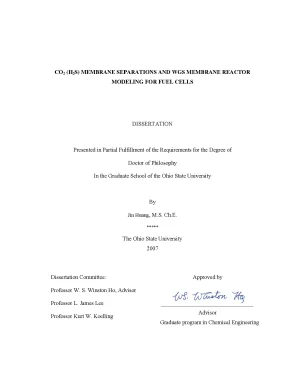
Tải xuống để đọc toàn bộCO2 (H2S) MEMBRANE SEPARATIONS AND WGS MEMBRANE REACTOR MODELING FOR FUEL CELLS DISSERTATION Presented in Partial Fulfillment of the Requirements for the Degree of Doctor of Philosophy In the Graduate School of the Ohio State University By Jin Huang, M. ***** The Ohio State University 2007 Dissertation Committee: Approved by Professor W. Winston Ho, Advisor Professor L. James Lee _____________________________________________________________________________ _ Advisor Professor Kurt W.
Koelling Graduate program in Chemical Engineering UMI Number: 3241691 UMI Microform 3241691 Copyright 2007 by ProQuest Information and Learning Company. All rights reserved. This microform edition is protected against unauthorized copying under Title 17, United States Code. ProQuest Information and Learning Company 300 North Zeeb Road P.
Box 1346 Ann Arbor, MI 48106-1346 ABSTRACT Acid-gas removal is of great importance in many environmental or energy-related processes. Compared to current commercial technologies, membrane-based CO2 and H2S capture has the advantages of low energy consumption, low weight and space requirement, simplicity of installation / operation, and high process flexibility. However, the large-scale application of the membrane separation technology is limited by the relatively low transport properties. In this study, CO2 (H2S)-selective polymeric membranes with high permeability and high selectivity have been studied based on the facilitated transport mechanism.
The membrane showed facilitated effect for both CO2 and H2S. A CO2 permeability of above 2000 Barrers, a CO2/H2 selectivity of greater than 40, and a CO2/N2 selectivity of greater than 200 at 100 – 150oC were observed. As a result of higher reaction rate and smaller diffusing compound, the H2S permeability and H2S/H2 selectivity were about three times higher than those properties for CO2. The novel CO2-selective membrane has been applied to capture CO2 from flue gas and natural gas.
In the CO2 capture experiments from a gas mixture with N2 and H2, a permeate CO2 dry concentration of greater than 98% was obtained by using steam as the sweep gas. In CO2/CH4 separation, decent CO2 transport properties were obtained with a feed pressure up to 500 psia. With the thin-film composite membrane structure, significant increase on the CO2 flux was achieved with the decrease of the selective layer thickness. ii With the continuous removal of CO2, CO2-selective water-gas-shift (WGS) membrane reactor is a promising approach to enhance CO conversion and increase the purity of H2 at process pressure under relatively low temperature.
The simultaneous reaction and transport process in the countercurrent WGS membrane reactor was simulated by using a one-dimensional non-isothermal model. The modeling results show that a CO concentration of less than 10 ppm and a H2 recovery of greater than 97% are achievable from reforming syngases. In an experimental study, the reversible WGS was shifted forward by removing CO2 so that the CO concentration was significantly decreased to less than 10 ppm. The modeling results agreed well with the experimental data.
iii Dedicated to my parents, my brother and Yujun for their love and support iv ACKNOWLEDGMENTS I would like to thank the following people for their help and support in conducting this research: • Dr. Winston Ho, my advisor at Ohio State, for his thoughtful guidance, enthusiastic discussion and continuous support and encouragement throughout the five years I have been in the United States. His persistence in pursuing the truth and his hard-working attitude have been, and will be, inspiring my career and life in the past and in the future. James Lee, Dr.
David Tomasko, and Dr. Barbara Wyslouzil for all their constructive critiques which helped me to improve my work. • I thank all my colleagues in Dr. Ho’s group: He Bai, Philip Chang, Bishnupada Mandal, Michael Vilt, Chi Yen, Jian Zou, and fellow students in Koffolt Labs who have to remain unnamed here.
Also I would like to thank the following people: • My friends, both in US and China, for all their encouragements and friendship. • My parents and my brother for their support and love throughout my studies over the years. v • Yujun for her support, encouragements, patience, and love while writing this thesis. vi VITA April 19, 1977.Born in Jianli, Hubei, China 1996.
Organic Chemical Technology, Wuhan Institute of Chemical Technology, Wuhan, China 1999. Chemical Engineering, East China Univ. of Science & Technology, Shanghai, China 2001 – 2002 .Graduate Research Associate, University of Kentucky, Lexington, KY, USA 2002 – 2006.Graduate Research Associate, The Ohio State University, Columbus, OH, USA PUBLICATIONS 1. Jin Huang, Louei El-Azzami, and W.
Winston Ho, “Modeling of CO2-selective Water- Gas-Shift Membrane Reactor for Fuel Cell,” J. Jian Zou, Jin Huang, and W. Winston Ho, “CO2-Selective Water gas shift Membrane Reactors for Fuel Cell Hydrogen Processing,” accepted by Ind. Ruofei Zhao, Jin Huang, Bin Sun, and Gance Dai, “A Study of Mechanical Properties of Mica Filled Polypropylene Based GMT Composites,” J.
Hui-ling Lu, Jin Huang, and Gance Dai, “Effects of Processing Parameters on Melt Impregnation of GMT Sheets,” J. East China Univ. Ming Li, Jin Huang, and Gance Dai, “Melt Flow through Glass Fiber Mat during GMT Melt Impregnation,” Acta Materiae Compositae Sinica, 17(3), pp. FIELDS OF STUDY Major Field: Chemical Engineering viii TABLE OF CONTENTS Abstract……………………………………………….vii List of Tables………………………….xiii List of Figures………………………………………………………………….xiv List of Notations……………………………………………………………….1 Membrane Separation Technology…………….2 Acid-gas Removal…………….3 Scope and Objectives of Research……………………………………………….
Synthesis of CO2 (H2S)-Selective Membrane……………….1 Polymeric Membrane for Gas Separation………………………………….2 Reaction Mechanism between Amines and Acid Gases………………….3 Facilitated Transport Membrane for Acid-gas Removal………………….2 CO2 (H2S)-Selective Membrane……….1 Membrane Synthesis and Characterization……………………………….3 CO2 Transport Properties…………………………………………………. Flue Gas CO2 Removal….2 CO2 Capture Experiments……………………………………………………….4 Results and Discussion………………………………………….1 Transport Properties of CO2-selective Membrane ……………………….2 CO2 Removal Capacity…………………………………………………….3 CO2 Capture Performance.1 Effect of Feed Inlet Flow Rate……………………………………….2 Effect of Sweep-to-Feed Ratio………………………………………. High-Pressure CO2 and H2S Removal from Natural Gas.3 Results and Discussion………………………………………………………….1 Free-Standing Membrane………………………………………………….1 Effect of Feed Pressure on CO2 Transport Properties……………….2 Effect of Temperature on CO2 Transport Properties…………….3 Effect of Permeate Pressure on CO2 Transport Properties………….2 Thin-Film Composite Membrane………………………………………….1 Effect of Membrane Thickness on CO2 Transport Properties….2 Effect of Temperature on CO2 and H2S Transport Properties………. Other CO2-Selective Membranes…………………………………………………….2 Hybrid Facilitated Transport Membrane………………………….1 Synthesis of Hybrid Membrane………………………………………….2 Results and Discussion………………………………………………….3 Segmented Polyimide Copolymer…………………………………………….1 Membrane Synthesis and Testing……………………………………….2 Results and Discussion………………………………………………….
Modeling of CO2-selective WGS membrane reactor for fuel cells.3 Experimental Study of CO2-Selective WGS Membrane Reactor …………….4 Results and Discussion…………………………………………………………130 6.1 Autothermal Reforming Syngas………………………………………….2 Effect of CO2/H2 Selectivity……………………………………….3 Effect of CO2 Permeability…………………………………………133 6.4 Effect of Sweep-to-Feed Ratio…………………………………….5 Effect of Inlet Feed Temperature………………………………….6 Effect of Inlet Sweep Temperature…………………………………135 6.7 Effect of Feed-Side Pressure……………………………………….8 Effect of Inlet Feed CO Concentration…………………………….9 Effect of Catalyst Activity………………………………………….2 Steam Reforming Syngas…………………………………………………138 6.2 Effect of CO2/H2 Selectivity……………………………………….3 Effect of CO2 Permeability…………………………………………140 6.4 Effect of Sweep-to-Feed Ratio…………………………………….5 Effect of Inlet Feed Temperature………………………………….6 Effect of Inlet Sweep Temperature…………………………………142 6.7 Effect of Feed-Side Pressure……………………………………….8 Effect of Feed Inlet CO Concentration…………………………….9 Effect of Catalyst Activity………………………………………….3 Membrane Reactor Results………………………………………………. Conclusions and recommendations………………………………………………….1 CO2 (H2S)-selective polymeric membranes and applications………………….2 Recommendations for Future Work…………………………………………….182 Bibliography……………………………………………………………………………185 xii LIST OF TABLES Table Page 2.1 Carbamate stability constants for different amines at 40oC by carbon-13 NMR (Sartori and Savage, 1983) ………………………………………………………30 3.1 The operating parameters for the CO2 capture experiments…………………….1 Diols as the option of soft segment…………………………………………….2 The testing results of copolymer membrane……………………………………109 6.1 The compositions of autothermal reforming syngas and steam reforming syngas………………………………………………………………………….147 xiii LIST OF FIGURES Figure Page 2.1 Facilitated transport mechanism…………………………………………………31 2.2 Synthesis of the crosslinked PVA with formaldehyde.3 Chemical structures of (a) free polyallylamine and (b) AIBA-K……………….4 Schematic of the gas permeation unit……………………………………………34 2.5 Scanning electron microscopic picture of the membrane synthesized………………35 2.6 CO2 permeability vs.7 CO2/H2 selectivity vs.8 CO2/N2 selectivity vs.9 H2S and CO2 permeability vs.10 H2S/H2 and CO2/H2 selectivity vs.11 H2S removal capacity with the circular gas permeation cell (24.1 Schematic of the hollow-fiber membrane module……………………………….2 Schematic of gas separation with the CO2-selective membrane…………………….3 Exit dry CO2 concentration in the retentate vs. feed flow rate………………….4 Permeate CO2 dry concentration and CO2 recovery vs. feed flow rate………….5 Permeate CO2 dry concentration and CO2 recovery vs.
sweep-to-feed molar ratio………………….6 CO2 concentration (wet) profiles along the length of membrane module…….1 Schematic of gas separation with the CO2 (H2S)-selective membrane………….2 CO2 permeability and CO2/CH4 selectivity vs. feed pressure at 106oC………….3 CO2 permeability and CO2/CH4 selectivity vs. feed pressure at 116oC………….4 CO2 permeability and CO2/CH4 selectivity vs. temperature at 150 psia feed pressure………………………………………………………………………….5 CO2 permeability and CO2/CH4 selectivity vs.
temperature at 500 psia feed pressure………………………………………………………………………….6 CO2 permeability and CO2/CH4 selectivity vs. permeate pressure at 106oC and 500 psia feed pressure……………………………………………………………85 4.7 CO2 permeability and CO2/CH4 selectivity vs. permeate pressure at 111oC and 500 psia feed pressure……………………………………………………………86 4.8 CO2 permeability and CO2/CH4 selectivity vs. permeate pressure at 116oC and 500 psia feed pressure……………………………………………………………87 4.9 CO2 permeance and CO2/CH4 selectivity vs.
membrane thickness at 116oC and 150 psia feed pressure……………………………………………………………88 4.10 Total mass transfer resistance, Rt, versus membrane thickness………………….11 CO2/CH4 and H2S/CH4 selectivities versus operating temperature…………….12 CO2 and H2S permeances versus operating temperature……………………….13 Schematic of the phase inversion process with the delayed demixing (■ denotes the top of the liquid film, ● denotes the bottom of the liquid film, and red lines denote the composition path along the liquid film thickness) ………………….14 The weight reduction of the membrane during the air-drying (23oC, casting gap setting = 10 mil) …………………………………………………………………93 4.15 The preliminary data from the asymmetric membranes via the phase inversion process (106oC and 150 psia feed pressure) …………………………………….1 CO2/H2 selectivity of PVA membrane and hybrid PVA membrane……………110 5.2 CO2/N2 selectivity of PVA membrane and hybrid PVA membrane……………111 5.3 CO2 permeability of PVA membrane and hybrid PVA membrane.4 The thermogravimetric curves for the hybrid PVA membrane and the PVA membrane……………………………………….5 Reaction steps in the synthesis of 2 PMDA/ 1 PEA 2000/ 1 MDA….6 FTIR spectra of copolymer, 2 PMDA / 1 PEA 2000 / 1 MDA, after imidization…………………………………………………………………….1 Schematic of water-gas-shift hollow-fiber membrane reactor………………….2 Cross-section schematic of the water-gas-shift membrane reactor…………….3 Feed-side CO and CO2 mole fraction profiles along the length of membrane reactor for autothermal reforming syngas………………………………………150 6.4 Feed-side H2 mole fraction profiles along the length of membrane reactor for autothermal reforming syngas………………………………………………….5 Feed-side and sweep-side temperature profiles along the length of membrane reactor for autothermal reforming syngas………………………………………152 6.6 The effects of CO2/H2 selectivity on feed-side exit CO concentration and H2 recovery for autothermal reforming syngas…………………………………….7 The effect of CO2 permeability on required membrane area for autothermal reforming syngas………………………………………….8 The effects of sweep-to-feed ratio on feed-side exit CO concentration and H2 recovery for autothermal reforming syngas……………………………….9 The effect of inlet feed temperature on required membrane area for autothermal reforming syngas………………………………………………………….10 Feed-side temperature profiles along the length of membrane reactor for autothermal reforming syngas with different inlet feed temperatures……….11 The effect of inlet sweep temperature on required membrane area for autothermal reforming syngas……………………………………………………………….12 Feed-side temperature profiles along the length of membrane reactor for autothermal reforming syngas with different inlet sweep temperatures……….13 The effect of feed-side pressure on required membrane area for autothermal reforming syngas……………………………………………………………….14 Feed-side CO mole fraction profiles along the length of membrane reactor for autothermal reforming syngas with different inlet feed CO temperatures…….15 The effect of catalyst activity on required membrane area for autothermal reforming syngas……………………………………………………………….16 Feed-side CO and CO2 mole fraction profiles along the length of membrane reactor for steam reforming syngas…………………………………………….17 Feed-side H2 mole fraction profiles along the length of membrane reactor for steam reforming syngas……………………………………………………….18 Feed-side and sweep-side temperature profiles along the length of membrane reactor for steam reforming syngas…………………………………………….19 The effects of CO2/H2 selectivity on feed-side exit CO concentration and H2 recovery for steam reforming syngas………………………………………….20 The effect of CO2 permeability on required membrane area for steam reforming syngas………………………………………………………………………….21 The effects of sweep-to-feed ratio on feed-side exit CO concentration and H2 recovery for steam reforming syngas………………………………………….22 The effect of inlet feed temperature on required membrane area for steam reforming syngas……………………………………………………………….23 Feed-side temperature profiles along the length of membrane reactor for steam reforming syngas with different inlet feed temperatures……………………….24 The effect of inlet sweep temperature on required membrane area for steam reforming syngas……………………………………………………………….25 Feed-side temperature profiles along the length of membrane reactor for steam reforming syngas with different inlet sweep temperatures…………………….26 The effect of feed-side pressure on required membrane area for steam reforming syngas………………………………………………………………………….
Nội dung được bảo vệ bản quyền — Tải xuống đầy đủ
Trích dẫn luận án này
Jin Huang (2007). CO2 H2S Membrane Separations WGS Reactor Fuel Cells [Luận án tiến sĩ, The Ohio State University]. LuanAn.net. https://luanan.net/ky-thuat-hoa-hoc-thuc-pham/cong-nghe-hoa-hoc/luan-an-tien-si-tach-co2-h2s-wgs-membrane-reactor-fuel-cells
Từ khóa và chủ đề nghiên cứu
Từ khóa liên quan
Xem thêm luận án cùng lĩnh vực
Chủ đề nghiên cứu
Câu hỏi thường gặp
Luận án "CO2 H2S Membrane Separations WGS Reactor Fuel Cells" nghiên cứu về vấn đề gì?
Luận án tiến sĩ công nghệ tách CO2 và H2S bằng màng polymer. Mô hình WGS membrane reactor cho pin nhiên liệu đạt nồng độ CO2 >98% và khôi phục H2 >97%.
Luận án "CO2 H2S Membrane Separations WGS Reactor Fuel Cells" được bảo vệ tại trường nào?
Luận án này được bảo vệ tại The Ohio State University. Năm bảo vệ: 2007.
Luận án "CO2 H2S Membrane Separations WGS Reactor Fuel Cells" thuộc chuyên ngành gì?
Luận án "CO2 H2S Membrane Separations WGS Reactor Fuel Cells" thuộc chuyên ngành Chemical Engineering. Danh mục: Công Nghệ Hóa Học.
Luận án "CO2 H2S Membrane Separations WGS Reactor Fuel Cells" có bao nhiêu trang?
Luận án "CO2 H2S Membrane Separations WGS Reactor Fuel Cells" có 217 trang. Bạn có thể xem trước một phần tài liệu ngay trên trang web trước khi tải về.
Cách tải luận án "CO2 H2S Membrane Separations WGS Reactor Fuel Cells" về máy như thế nào?
Để tải luận án về máy, bạn nhấn nút "Tải xuống ngay" trên trang này, sau đó hoàn tất thanh toán phí lưu trữ. File sẽ được tải xuống ngay sau khi thanh toán thành công. Hỗ trợ qua Zalo: 0559 297 239.