Shear strength, creep và stability của fiber-reinforced soil slopes - Garry Haden Gregory
Luận án tiến sĩ nghiên cứu độ bền cắt, creep và ổn định sườn đất tăng cường bằng sợi. Phân tích thực nghiệm, mô hình lý thuyết và ứng dụng kỹ thuật xây dựng.
Năm xuất bản
Số trang
242
Thời gian đọc
37 phút
Lượt xem
2
Lượt tải
0
Phí lưu trữ
50 Point
Tổng quan nhanh
- Chủ đề:
- 1. Fiber-Reinforced Soil Slopes: Shear Strength Overview
- Số trang:
- 242 trang
- Trường:
- Oklahoma State University
- Chuyên ngành:
- Kỹ thuật xây dựng
- Tác giả:
- Garry Haden Gregory
- Năm:
- 2006
Tóm tắt nội dung luận án
I. Fiber Reinforced Soil Slopes Shear Strength Overview
Fiber-reinforced soil (FRS) technology transforms conventional geotechnical engineering through discrete fiber inclusion. The methodology enhances soil mechanical properties without complex installation procedures. Research demonstrates significant improvements in shear strength parameters when fibers integrate with soil matrices. The doctoral dissertation by Gregory (2006) provides comprehensive analysis of fiber-soil interaction mechanisms. Laboratory testing programs evaluated both cohesive and granular soils under various loading conditions. Triaxial compression tests, direct shear tests, and unconfined compressive strength measurements quantified strength enhancement. Results indicate fiber content optimization directly influences slope stability performance. The fiber reinforcement mechanism operates through tensile resistance and soil-fiber interaction at particle level. Cohesion enhancement occurs as fibers create three-dimensional reinforcement networks. Friction angle modifications depend on fiber aspect ratio and fiber length ratio parameters. Testing protocols included clay and silty sand specimens with varying fiber concentrations. Data correlation revealed predictable relationships between fiber parameters and strength gains. The conceptual model developed enables practical application in slope design. Field case histories validated laboratory findings across multiple construction projects. Implementation success depends on proper fiber content optimization and compaction control. The research establishes foundational principles for FRS slope stability analysis.
1.1. Fundamental Mechanisms of Fiber Reinforcement
Fiber reinforcement mechanism functions through tensile load transfer between soil particles. Individual fibers mobilize when soil mass experiences shear deformation. The soil-fiber interaction creates anchorage through surface friction and mechanical interlocking. Fiber aspect ratio (length-to-diameter ratio) determines effectiveness of load distribution. Longer fibers develop greater tensile resistance but require adequate mixing protocols. The three-dimensional random distribution provides isotropic strength enhancement. Unlike planar reinforcement systems, discrete fibers reinforce in all directions simultaneously.
1.2. Laboratory Testing Methodology Framework
Comprehensive testing program employed triaxial compression test and direct shear test procedures. Specimens underwent careful preparation to ensure uniform fiber distribution throughout soil matrix. Unconfined compressive strength tests provided baseline strength characterization. Consolidation and saturation phases preceded shear testing for cohesive specimens. Electronic data acquisition systems captured stress-strain relationships continuously. Post-test specimen dissection verified fiber orientation and distribution patterns. Multiple fiber content levels enabled correlation development between reinforcement and strength parameters.
1.3. Critical Parameters Affecting Performance
Fiber content optimization balances strength enhancement against workability constraints. Excessive fiber concentrations create mixing difficulties and reduce compaction efficiency. Fiber length ratio influences the effective anchorage zone within soil mass. Optimal aspect ratios vary between cohesive and granular soil types. Moisture content during compaction affects fiber distribution uniformity. Testing revealed specific threshold values for maximum effectiveness in different soil classifications.
II. Shear Strength Enhancement Through Fiber Inclusion
Shear strength parameters exhibit measurable improvement when fibers integrate into soil matrices. The research quantified cohesion enhancement and friction angle modifications separately. Triaxial compression test results demonstrated consistent strength gains across confining pressure ranges. Direct shear test data confirmed findings under different boundary conditions. Cohesive strength correlations showed linear relationships with fiber content up to threshold values. Beyond optimal concentrations, strength gains diminished due to fiber-fiber interference. The fiber reinforcement mechanism contributes both apparent cohesion and frictional components. Soil-fiber interaction generates tensile resistance that restrains particle movement during shearing. Clay specimens showed greater cohesion enhancement compared to friction angle changes. Sandy soils exhibited more balanced improvements in both strength parameters. Fiber aspect ratio proved critical for mobilizing tensile capacity effectively. Short fibers pulled out before developing full tensile strength. Long fibers occasionally experienced breakage at high strain levels. The fiber length ratio (fiber length to specimen dimension) influenced boundary effects. Testing protocols maintained consistent compaction energy to isolate fiber effects. Unconfined compressive strength increased proportionally with fiber content in cohesive soils. The conceptual model incorporated both reinforcement components for predictive calculations.
2.1. Cohesion Enhancement Mechanisms
Cohesion enhancement results from apparent cohesion generated by fiber tensile resistance. Randomly distributed fibers create three-dimensional reinforcement networks throughout soil mass. When shear planes develop, fibers crossing the failure surface mobilize tensile forces. These forces provide additional resistance beyond natural soil cohesion. Clay specimens demonstrated cohesion increases ranging from 50% to 300% depending on fiber content. The soil-fiber interaction depends on adequate anchorage length on both sides of shear plane. Surface characteristics of fibers influence bond strength with clay particles.
2.2. Friction Angle Modifications
Friction angle changes occur through different mechanisms than cohesion enhancement. Fibers increase apparent friction by restraining particle rotation and translation. The fiber aspect ratio determines effectiveness of this restraint mechanism. Granular soils showed friction angle increases of 2 to 8 degrees with optimal fiber content. Dense sand matrices benefit less than loose configurations due to initial particle interlocking. Fiber orientation relative to shear direction influences frictional contribution magnitude.
2.3. Combined Strength Parameter Effects
Total shear strength improvement combines cohesion enhancement and friction angle modifications. The Mohr-Coulomb failure envelope shifts upward and rotates with fiber inclusion. Triaxial compression test results plotted as stress paths show consistent envelope adjustments. Direct shear test data confirmed similar trends under constant normal stress conditions. Fiber content optimization requires balancing both strength components for specific applications. Design charts developed from test data enable selection of appropriate fiber concentrations.
III. Creep Behavior of Fiber Reinforced Soil Systems
Creep behavior evaluation addressed long-term deformation characteristics under sustained loading. Custom-designed direct shear creep devices enabled extended duration testing. Clay specimens underwent saturation and consolidation before creep shear stages. Applied shear stresses represented percentages of peak strength from conventional tests. Electronic data acquisition monitored displacement continuously over weeks and months. Results demonstrated that fiber inclusion significantly reduced creep rates. Unreinforced clay specimens exhibited primary, secondary, and tertiary creep phases. Fiber-reinforced specimens showed suppressed secondary creep rates and delayed tertiary failure. The fiber reinforcement mechanism provides sustained tensile resistance during creep deformation. Soil-fiber interaction maintains effectiveness under constant stress conditions. Fiber content optimization for creep resistance differed slightly from peak strength optimization. Higher fiber concentrations provided better long-term stability under sustained loads. Time-dependent behavior correlations developed for various fiber content levels. The research established that fibers do not experience significant relaxation under soil confinement. Creep strain magnitudes reduced by 40% to 70% with optimal fiber reinforcement. Applications requiring long-term stability benefit substantially from fiber inclusion. Slope stability analysis must consider both peak strength and creep characteristics.
3.1. Creep Testing Apparatus and Procedures
Specialized creep devices fabricated in-house enabled controlled long-duration testing. Direct shear box configuration allowed constant normal stress application during creep phase. Lever arm systems maintained constant shear stress through dead weight loading. Saturation and consolidation procedures matched conventional direct shear test protocols. Electronic displacement transducers measured horizontal and vertical movements continuously. Data logging systems recorded readings at programmed intervals ranging from minutes to hours. Multiple specimens tested simultaneously under different stress levels provided comparative data.
3.2. Creep Rate Reduction Mechanisms
Fiber reinforcement mechanism suppresses creep through continuous tensile resistance mobilization. Unlike peak strength conditions, creep involves gradual particle rearrangement under constant stress. Fibers restrain progressive particle movement that characterizes secondary creep phase. The soil-fiber interaction remains effective during slow deformation processes. Random fiber orientation ensures reinforcement regardless of creep deformation direction. Fiber aspect ratio influences long-term anchorage stability within creeping soil mass.
3.3. Long Term Stability Implications
Reduced creep rates directly improve long-term slope stability under sustained loading conditions. Embankments and slopes experience continuous gravitational stresses requiring creep resistance. Fiber-reinforced soil slopes demonstrate enhanced performance over decades of service life. Time-dependent deformation predictions require creep test data for accurate modeling. Design factors of safety can potentially decrease when accounting for fiber creep resistance. Field monitoring of case history projects confirmed laboratory creep behavior predictions.
IV. Slope Stability Analysis Methods for FRS
Slope stability analysis methodology requires modifications to incorporate fiber reinforcement effects. Conventional limit equilibrium methods apply with adjusted strength parameters. The research developed calibrated relationships between fiber content and shear strength values. Existing computer programs accept modified cohesion and friction angle inputs. Analysis procedures treat fiber-reinforced soil as improved material with enhanced properties. Factor of safety calculations increase proportionally with fiber-induced strength gains. The conceptual model enables prediction of strength parameters from fiber content specifications. Triaxial compression test data provided calibration for various soil types and fiber concentrations. Direct shear test results validated strength parameters under different stress conditions. Slope geometry and loading conditions follow standard geotechnical analysis procedures. Critical failure surfaces identified through conventional search algorithms. Fiber content optimization balances cost against required stability improvements. Design charts facilitate selection of appropriate reinforcement levels for target safety factors. Case history projects demonstrated successful application of modified analysis methods. Field performance matched predicted stability improvements from laboratory-calibrated parameters. Implementation requires quality control during construction to ensure specified fiber distribution. Compaction procedures must maintain fiber integrity and uniform mixing throughout soil mass.
4.1. Modified Limit Equilibrium Approaches
Limit equilibrium methods incorporate fiber effects through enhanced strength parameters in Mohr-Coulomb equations. Cohesion enhancement values derived from triaxial compression test and direct shear test data. Friction angle modifications applied based on soil type and fiber content optimization results. Circular and non-circular failure surface analyses both accommodate adjusted parameters. Bishop's simplified method and Spencer's method produce comparable results with fiber-reinforced soils. Computer programs require minimal modification to accept enhanced strength inputs.
4.2. Calibration from Laboratory Testing
Calibration procedures correlate laboratory test results with field-scale performance predictions. Triaxial compression test specimens provide stress-strain relationships under confining pressures. Direct shear test data offers complementary information under constant normal stress conditions. Unconfined compressive strength tests characterize cohesive soil improvement efficiently. The fiber reinforcement mechanism scales from laboratory to field applications through proper correlation. Soil-fiber interaction principles remain consistent across specimen sizes when fiber length ratio maintains appropriate values.
4.3. Design Implementation Procedures
Design process begins with site-specific soil characterization and stability requirements. Target factor of safety determines required strength enhancement magnitude. Fiber content optimization identifies economical reinforcement level achieving stability goals. Construction specifications detail fiber type, length, aspect ratio, and mixing procedures. Quality control testing verifies proper fiber distribution and compaction density. Post-construction monitoring validates design assumptions and long-term performance predictions.
V. Soil Fiber Interaction and Interface Behavior
Soil-fiber interaction mechanisms govern reinforcement effectiveness at microscopic and macroscopic scales. Interface shear tests quantified bond strength between individual fibers and soil matrices. Clay soils develop adhesive bonds with fiber surfaces through electrochemical attraction. Sandy soils rely on mechanical interlocking and frictional resistance for fiber anchorage. Fiber aspect ratio determines available surface area for interface stress transfer. Rough fiber surfaces generate higher interface shear strength than smooth fibers. The fiber reinforcement mechanism requires adequate anchorage length for full tensile mobilization. Pull-out tests indicated minimum embedment lengths for various soil types and fiber diameters. Interface behavior differs between cohesive and granular soils due to particle size effects. Clay particles coat fiber surfaces creating composite interaction zones. Sand grains indent into fiber surfaces under confining pressure enhancing mechanical interlock. Moisture content influences interface strength in cohesive soils through consistency changes. Fiber length ratio must account for specimen boundaries to avoid edge effects during testing. Triaxial compression test specimens exhibited uniform fiber distribution when properly mixed. Direct shear test specimens sometimes showed preferential fiber orientation near shear plane. Post-test dissection revealed fiber stretching, pull-out, and occasional breakage depending on stress levels. The conceptual model incorporated interface strength parameters for predictive calculations.
5.1. Interface Shear Strength Characterization
Interface shear tests isolated fiber-soil bond strength from composite material behavior. Single fiber pull-out tests measured peak resistance and post-peak sliding friction. Clay interfaces developed adhesive bonds ranging from 20% to 60% of soil cohesion. Sandy soil interfaces generated frictional resistance proportional to confining pressure. Fiber surface texture significantly influenced interface shear capacity. Synthetic fibers with crimped or roughened surfaces outperformed smooth fibers. Normal stress on interface controlled mechanical interlocking component of bond strength.
5.2. Anchorage Length Requirements
Minimum anchorage length ensures fibers develop tensile capacity before pull-out occurs. The fiber aspect ratio combines with interface strength to determine required embedment. Clay soils required shorter anchorage lengths due to adhesive bonding mechanisms. Sandy soils needed longer embedment to mobilize sufficient frictional resistance. Fiber length ratio in test specimens maintained values preventing boundary interference. Optimal fiber lengths balanced anchorage requirements against mixing workability constraints.
5.3. Failure Mode Observations
Post-test specimen dissection identified three primary fiber failure modes. Pull-out failure occurred when anchorage length proved insufficient for applied stress. Fiber breakage happened at high strain levels exceeding tensile capacity. Stretching without failure indicated proper anchorage and ductile fiber behavior. Triaxial compression test specimens predominantly showed fiber stretching with occasional breakage. Direct shear test specimens exhibited mixed failure modes depending on fiber orientation relative to shear plane. Understanding failure modes guides fiber selection and content optimization for specific applications.
VI. Practical Applications and Case History Validation
Field implementation of fiber-reinforced soil technology validated laboratory research findings across multiple projects. The PGBT Turnpike project demonstrated successful embankment construction using FRS methodology. Steep slope angles achieved through fiber inclusion reduced right-of-way requirements. Construction procedures adapted conventional earthwork practices to accommodate fiber mixing. Batch mixing at central plant ensured uniform fiber distribution before placement. Compaction equipment and methods matched standard specifications with minor adjustments. Quality control testing verified fiber content and density requirements during construction. Post-construction monitoring confirmed stability predictions from laboratory-calibrated analysis methods. Long-term performance observations showed minimal deformation and no distress signs. Cost analysis indicated fiber reinforcement provided economical alternative to conventional stabilization methods. The fiber content optimization process balanced material costs against reduced earthwork quantities. Fiber aspect ratio selection considered both performance requirements and mixing capabilities. Case histories encompassed various soil types including clays, silty sands, and mixed materials. Slope heights ranged from small roadway embankments to major highway earth structures. Geographic locations varied from humid to arid climates testing durability under different conditions. Lessons learned from field applications refined design procedures and construction specifications. The technology proved particularly valuable for projects with limited right-of-way or difficult foundation conditions.
6.1. Construction Implementation Methods
Successful field implementation requires adapted construction procedures maintaining fiber integrity. Central plant mixing provides better fiber distribution uniformity than in-place mixing. Batch quantities balanced production efficiency against fiber dispersion requirements. Mixing duration and intensity ensured individual fiber separation without breakage. Moisture content control during mixing affected both fiber distribution and compaction characteristics. Placement procedures avoided fiber segregation during hauling and spreading operations. Compaction equipment selection considered fiber presence without special modifications needed.
6.2. Quality Control and Verification Testing
Field quality control programs verified fiber content through wash-out tests on compacted samples. Density testing followed standard procedures with acceptance criteria matching unreinforced soil requirements. Visual inspection during mixing confirmed proper fiber distribution and separation. Test sections established appropriate compaction methods before full-scale production. Unconfined compressive strength tests on field samples validated laboratory predictions. Direct shear test data from field samples confirmed strength parameter assumptions used in design.
6.3. Performance Monitoring and Cost Analysis
Long-term monitoring programs tracked deformation, settlement, and distress indicators. Survey monuments measured slope movement over months and years following construction. Visual inspections documented surface conditions and vegetation establishment. Performance data confirmed laboratory creep predictions and stability analysis assumptions. Cost comparisons showed fiber reinforcement competitive with alternative stabilization methods. Reduced earthwork quantities from steeper slopes offset fiber material costs. Overall project savings resulted from smaller footprints and faster construction schedules.
Mục lục chi tiết luận án
Tải xuống file đầy đủ để xem toàn bộ nội dung
Tải đầy đủ (242 trang)Nội dung chính
Tổng quan về luận án
Nghiên cứu của Garry Haden Gregory (2006) tại Đại học Bang Oklahoma (Oklahoma State University) dưới sự hướng dẫn của GS. Dr. Snethen mang tựa đề "Shear Strength, Creep and Stability of Fiber-Reinforced Soil Slopes" là công trình tiên phong giải quyết bài toán cơ học đất gia cố sợi (Fiber-Reinforced Soil - FRS). Trong khi vật liệu địa kỹ thuật tổng hợp dạng phẳng (planar geosynthetics) như vải địa kỹ thuật (geotextiles) và lưới địa kỹ thuật (geogrids) đã có khung tính toán hoàn chỉnh (Koerner, 1994), việc ứng dụng các sợi polymer ngắn phân tán ngẫu nhiên nhằm gia cường khối đất 3 chiều vẫn thiếu hụt nền tảng lý thuyết định lượng và mô hình giải tích chuẩn mực.
Khoảng trống nghiên cứu (research gap) cốt lõi xuất phát từ thực trạng: hầu hết các nghiên cứu cơ sở trước đó (Gray & Ohashi, 1983; Maher & Gray, 1990; Benson & Khire, 1994; Ranjan et al., 1996) chỉ tập trung vào đất rời không dính (cohesionless sand). Ngược lại, thực tiễn xây dựng đắp đập và ổn định mái dốc trượt đòi hỏi xử lý đất sét dẻo cao (cohesive fat clay) – loại đất có cường độ kháng cắt hữu hiệu dài hạn thấp và dễ biến dạng từ biến (creep). Luận án đặt ra và chứng minh 3 giả thuyết nghiên cứu chính:
- Hypothesis 1 ($H_1$): Sợi polypropylene phân tán đẳng hướng ngẫu nhiên trong môi trường nửa không gian (half-space continuum) chịu trường ứng suất pháp trung bình $K_e = (1 + 3K_0)/4$, tạo ra sự gia tăng đồng thời cả thành phần góc ma sát trong ($\Delta\phi_{frs}$) lẫn lực dính biểu kiến ($\Delta c_{frs}$).
- Hypothesis 2 ($H_2$): Tỷ số diện mạo hữu hiệu ($a_{re} = l / 2d$) chi phối trực tiếp lực kháng tuột sợi (pullout resistance) hơn là tỷ số hình học danh định ($l/d$).
- Hypothesis 3 ($H_3$): Cấu trúc vi sợi phân tán ngăn chặn sự tập trung ứng suất trượt, làm suy giảm đáng kể tốc độ biến dạng từ biến cắt và triệt tiêu nguy cơ sạt lở bề mặt mái dốc đất sét.
Khung lý thuyết của luận án tích hợp cơ học môi trường liên tục nửa không gian geostatic, lý thuyết phân bố xác suất không gian cầu của Maher & Gray (1990), và mở rộng tiêu chuẩn phá hoại Mohr-Coulomb tuyến tính với điểm xoay đường bao cường độ ($\sigma_r$). Phạm vi thực nghiệm của luận án bao gồm 101 mẫu nén ba trục cố kết không thoát nước (CU), cắt trực tiếp cố kết thoát nước (CD), và thí nghiệm từ biến cắt trực tiếp kéo dài với tổng thời gian vận hành phòng thí nghiệm đạt 7.693 giờ. Tác động của nghiên cứu được định lượng thông qua kiểm chứng mô hình trên cơ sở dữ liệu 330 mẫu nén ba trục từ AGT Laboratories và áp dụng thành công trên 2 dự án giao thông trọng điểm quy mô lớn tại Texas.
Literature Review và Positioning
Lịch sử gia cường đất bằng sợi bắt nguồn từ tập quán cổ xưa trộn rơm vào gạch bùn và cơ chế gia cường tự nhiên của hệ rễ cây trong việc gia tăng cường độ kháng cắt biểu kiến. Đến thập niên 1980, các nghiên cứu hàn lâm hiện đại bắt đầu định hình. Gray & Ohashi (1983) đã thực hiện loạt thí nghiệm cắt trực tiếp trên cát gia cố sợi tự nhiên và kim loại, thiết lập tiền đề về sự tồn tại của "ứng suất giam giữ tới hạn" (critical confining stress) – ranh giới phân định hai cơ chế phá hoại: tuột sợi (pullout) ở dải áp lực thấp và chảy dẻo/đứt sợi (yielding/rupture) ở dải áp lực cao. Maher & Gray (1990) tiếp tục phát triển mô hình phân bố xác suất của các sợi ngẫu nhiên trong không gian hình cầu 3D, chứng minh rằng sự cải thiện độ bền tỷ lệ thuận với tỷ số diện mạo sợi ($l/d$). Benson & Khire (1994) sử dụng dải nhựa tái chế từ bình polyethylene mật độ cao (HDPE) gia cố cát, xác định hệ số tương tác ma sát mặt tiếp xúc $f_\phi \approx 0{,}90$ và ghi nhận hiện tượng mẫu gia cố sợi duy trì tăng cường độ cắt ở dải biến dạng rất lớn vượt xa biến dạng đỉnh của đất nguyên dạng. Ranjan et al. (1996) ứng dụng hàm hồi quy logarit trên thí nghiệm nén ba trục của cát gia cố sợi, chỉ ra mối quan hệ gia tăng tuyến tính của cường độ kháng cắt lên tới tỷ lệ phối trộn $2{,}0%$ theo trọng lượng khô trước khi bước vào giai đoạn bão hòa.
Tuy nhiên, các tranh luận học thuật nổi lên xoay quanh hai luồng quan điểm trái ngược:
- Tranh luận về định hướng sợi: Gray & Ohashi (1983) chỉ ra góc nghiêng sợi $60^\circ$ so với mặt trượt mang lại hiệu quả gia cường tối ưu, trong khi Maher & Gray (1990) chứng minh việc định hướng sợi nhân tạo không đem lại khác biệt có ý nghĩa thống kê so với phân bố ngẫu nhiên đẳng hướng trong thi công thực tế. Luận án của Gregory giải quyết tranh luận này bằng cách mô hình hóa toán học xác suất định hướng đẳng hướng 3D kết hợp trường ứng suất địa tĩnh.
- Tranh luận về cơ chế gia cường trong đất dính: Các nghiên cứu tiền thời hoàn toàn xem nhẹ thành phần lực dính ($c$), mặc định sợi chỉ làm tăng ma sát. Gregory đã định vị nghiên cứu của mình vào đúng khoảng trống này: thiết lập mô hình giải tích cho đất dính (cohesive soil) và kiểm chứng trên đất sét dẻo cao Eagle Ford.
So sánh với các nghiên cứu quốc tế, công trình của Gregory vượt trội về quy mô khi đối chiếu và tổng hợp dữ liệu từ chương trình nghiên cứu của Fugro South (1995–1998) và dự án thử nghiệm quy mô 110 tổ hợp nén ba trục (330 mẫu) của AGT Laboratories (1998–2001), tạo nên một khung đánh giá có độ tin cậy thực nghiệm cao nhất trong lĩnh vực FRS tính đến thời điểm công bố.
Đóng góp lý thuyết và khung phân tích
Đóng góp cho lý thuyết
Luận án mở rộng trực tiếp lý thuyết cân bằng giới hạn Mohr-Coulomb và lý thuyết ứng suất địa tĩnh trong môi trường nửa không gian vô hạn thông qua 4 đóng góp đột phá:
+---------------------------------------------------------------------------------------------------+
| KHUNG MÔ HÌNH LÝ THUYẾT GREGORY CHO ĐẤT GIA CỐ SỢI (FRS)                                         |
+---------------------------------------------------------------------------------------------------+
| 1. Trường ứng suất pháp hữu hiệu sợi 3D:                                                          |
|    \sigma_v \cdot K_e  với  K_e = (1 + 3K_0) / 4                                                 |
|                                                                                                   |
| 2. Tỷ số diện mạo hữu hiệu và mật độ sợi cắt mặt trượt:                                          |
|    a_re = l / (2d)    và    N_f = 2V_r / (\pi d^2)                                                |
|                                                                                                   |
| 3. Gia tăng góc ma sát trong và Lực dính biểu kiến:                                               |
|    \Delta\phi_{frs} = \arctan [ a_re \cdot K_e \cdot f_\phi \cdot V_r \cdot \tan\phi ]            |
|    \tau_{frsc} = a_re \cdot f_c \cdot V_r \cdot c                                                 |
|                                                                                                   |
| 4. Hiệu chỉnh xoay đường bao cường độ tại điểm \sigma_r = c / \tan\phi:                          |
|    \Delta c_{frs} = \tau_{frsc} - \sigma_r (\tan\phi_{frs} - \tan\phi)                            |
|    c_{frs} = c + \Delta c_{frs}                                                                   |
|                                                                                                   |
| 5. Hàm suy giảm tiếp xúc sợi ở hàm lượng cao (Decay Function):                                    |
|    f_{\phi, \text{adj}} = f_\phi \cdot R_f(V_r); \quad f_{c, \text{adj}} = f_c \cdot R_f(V_r)    |
+---------------------------------------------------------------------------------------------------+
-
Thiết lập biến số ứng suất hữu hiệu $K_e$ cho sợi ngẫu nhiên 3D: Khác với vật liệu địa kỹ thuật phẳng chỉ chịu ứng suất đứng đè nặng $\sigma_v = \gamma z$, sợi phân bố ngẫu nhiên chịu đồng thời cả ứng suất đứng $\sigma_v$ lẫn ứng suất ngang $\sigma_h = K_0 \sigma_v$. Xét tính đối xứng phần tư không gian (quarter-space symmetry), ứng suất pháp trung bình dọc trục sợi là $(\sigma_v + \sigma_h)/2$, và ứng suất trên tiết diện ngang sợi là bình quân của sợi đứng ($\sigma_h$) và sợi ngang $[(\sigma_v + \sigma_h)/2]$. Tổng hợp lại, Gregory suy dẫn chính xác hệ số ứng suất hữu hiệu: $$\sigma_{\text{avg}} = \sigma_v \left( \frac{1 + 3K_0}{4} \right) = \sigma_v K_e$$ với $K_e = (1 + 3K_0)/4$.
-
Khái niệm tỷ số diện mạo hữu hiệu ($a_{re}$): Chiều dài hiệu dụng của một sợi đơn lẻ cắt qua mặt trượt biến thiên đều từ $0$ đến $l/2$, do đó giá trị kỳ vọng là $L_e = l/4$. Tích phân số lượng sợi $N_f$ giao cắt một đơn vị diện tích mặt trượt dẫn đến việc xác lập $a_{re} = l/(2d)$, thay thế cho tỷ số danh định $l/d$.
-
Mô hình hóa điểm xoay đường bao cường độ ($\sigma_r$): Khi gia cố sợi, góc ma sát tăng lên ($\Delta\phi_{frs} > 0$). Do đó, sự gia tăng lực dính không thể tịnh tiến song song đơn thuần theo công thức chưa hiệu chỉnh $\tau_{frsc} = a_{re} f_c V_r c$. Đường bao cường độ FRS sẽ xoay quanh điểm ứng suất chuẩn $\sigma_r = c / \tan\phi$. Lực dính biểu kiến thực tế $\Delta c_{frs}$ được hiệu chỉnh chính xác bằng: $$\Delta c_{frs} = \tau_{frsc} - \sigma_r (\tan\phi_{frs} - \tan\phi)$$
-
Bản chất cơ chế tương tác sợi - hạt đất: Bốn cơ chế thành phần được hợp nhất định lượng gồm: (a) ma sát tuột sợi (pullout resistance); (b) lực dính bám bề mặt sợi - hạt sét (adhesion); (c) sức chịu tải vi mô (micro-bearing capacity) khi sợi bị uốn gập qua mặt trượt; và (d) sự gia tăng ứng suất pháp cục bộ trong khối đất bao quanh sợi khi chịu kéo.
Khung phân tích độc đáo
Khung phân tích của luận án tích hợp đồng thời 3 trường lý thuyết: (1) Cơ học tiếp xúc phân giới đất - polymer thông qua hệ số tương tác ma sát $f_\phi$ và hệ số dính bám $f_c$; (2) Lý thuyết xác suất hình học không gian (Stereology); và (3) Cơ học từ biến phi tuyến.
Một điểm đột phá trong khung phân tích là hàm suy giảm (decay function). Khi hàm lượng sợi ($V_r$) vượt quá ngưỡng tối ưu ($> 0{,}25\text{ pcf}$ đến $0{,}50\text{ pcf}$), mật độ sợi quá lớn dẫn đến hiện tượng tiếp xúc sợi - sợi (fiber-to-fiber contact) thay vì sợi - đất (fiber-to-soil contact). Gregory đưa vào hệ số suy giảm tương tác để điều chỉnh giảm $f_\phi$ và $f_c$, phản ánh chính xác quy luật suy giảm biên trong vật liệu composite địa kỹ thuật.
Điều kiện biên áp dụng của mô hình được xác định rõ: áp dụng cho trường ứng suất giam giữ thấp hơn ứng suất tới hạn ($\sigma_3 < \sigma_{\text{crit}}$), bảo đảm cơ chế phá hoại chi phối là tuột sợi (pullout) mà không xảy ra hiện tượng đứt sợi hàng loạt – hoàn toàn phù hợp với độ sâu thực tế của các khối trượt mái dốc ($z < 15\text{ m}$).
Phương pháp nghiên cứu tiên tiến
Thiết kế nghiên cứu
Nghiên cứu tuân thủ chặt chẽ triết lý thực chứng (positivism) với phương pháp tiếp cận đa cấp độ (multi-level experimental design):
- Cấp độ vi mô/bề mặt tiếp xúc: Thí nghiệm cắt trực tiếp giao diện (Interface Shear Tests) trên hộp cắt lớn giữa tấm vật liệu polypropylene nguyên bản và đất nhằm xác định hệ số tương tác $f_\phi$ và $f_c$.
- Cấp độ trung mô (mẫu phòng thí nghiệm): Phân tích hệ thống mẫu đất sét dẻo cao và cát bột với các hàm lượng sợi biến thiên ($0$; $0{,}17$; $0{,}25$; $0{,}50$; $1{,}0$; $1{,}5$; $2{,}0\text{ pcf}$).
- Cấp độ vĩ mô: Đo đạc và mô phỏng trên các dự án thực tế hiện trường.
Hai loại đất đối chứng đại diện cho hai cận biên tính dẻo trong địa kỹ thuật đắp:
- Đất sét dẻo cao (Fat Clay - CH): Lấy từ thành tạo địa chất Eagle Ford (Bắc Trung bộ Texas), có giới hạn chảy $LL = 59$, giới hạn dẻo $PL = 20$, chỉ số dẻo $PI = 39$, tỷ lệ hạt qua rây No. 200 ($0{,}075\text{ mm}$) đạt $94%$.
- Cát bột không dẻo (Silty Sand - SM): Lấy từ Stillwater, Oklahoma, hoàn toàn không dẻo (NP), tỷ lệ hạt qua rây No. 200 là $13%$.
- Sợi gia cố: Sợi polypropylene thương phẩm dạng monofilament từ Synthetic Industries, chiều dài $l = 2{,}0\text{ inches}$ ($50\text{ mm}$), bề rộng $1{,}0\text{ mm}$, chiều dày $0{,}1\text{ mm}$, tỷ trọng $G_s = 0{,}91$.
Quy trình nghiên cứu rigorous
Quy trình chuẩn bị và thí nghiệm được chuẩn hóa nghiêm ngặt theo các tiêu chuẩn ASTM tương ứng:
- Xử lý mẫu số lượng lớn: Đất sét lấy từ ống mẫu thành mỏng Shelby Tube được hong khô tự nhiên 1 tuần, nghiền cơ học bằng máy nghiền đất chuyên dụng, trộn đều bằng phương pháp chia tư (quartering) để tạo ra mẫu khối lượng $400\text{ lbs}$ ($181{,}5\text{ kg}$). Đất cát được chuẩn bị với khối lượng $300\text{ lbs}$ ($136\text{ kg}$).
- Kiểm soát độ ẩm và đầm nén: Xác định đường cong đầm nén tiêu chuẩn theo ASTM D 698 (Standard Proctor) cho đất sét và ASTM D 4253 & D 4254 cho mật độ cát. Sợi được rải đều và trộn tay theo quy trình 3 giai đoạn để ngăn ngừa hiện tượng vón cục (balling/clumping), sau đó mẫu được dưỡng ẩm trong thùng kín chuyên dụng.
- Hệ thống nén ba trục cố kết không thoát nước (CU with pore pressure): Tiến hành trên buồng nén 3 trục tự động hóa với hệ thống thu thập dữ liệu điện tử (Electronic Data Acquisition). Áp lực nước lỗ rỗng ($u$), độ biến dạng trục ($\epsilon$) và ứng suất lệch ($\sigma_1 - \sigma_3$) được ghi nhận theo thời gian thực.
- Hệ thống thí nghiệm từ biến cắt trực tiếp (Direct Shear Creep): Tác giả đã tự thiết kế và gia công cơ khí các thiết bị cắt từ biến tải trọng không đổi (Direct Shear Creep devices) tại xưởng cơ khí Civil Engineering OSU, cho phép duy trì ứng suất cắt liên tục trong môi trường ngập nước suốt $504\text{ giờ}$/mẫu để theo dõi biến dạng từ biến theo thang thời gian logarit.
- Quy trình giải phẫu mẫu sau phá hoại (Dissection): Tất cả các mẫu sau khi cắt đều được giải phẫu cẩn thận để quan sát sự phân bố sợi, góc uốn của sợi tại mặt trượt, kiểm chứng trực quan cơ chế tuột sợi mà không bị đứt.
+---------------------------------------------------------------------------------------------------+
| TỔNG HỢP THỜI GIAN VẬN HÀNH THÍ NGHIỆM THỰC NGHIỆM (TỔNG CỘNG: 7.693 GIỜ)                       |
+------------------------------------+---------------+---------------------+------------------------+
| Hạng mục thí nghiệm                | Số lượng mẫu  | Đơn giá thời gian   | Tổng thời gian (Giờ)   |
+------------------------------------+---------------+---------------------+------------------------+
| Đầm nén Standard Proctor           | 10 mẫu        | 2 giờ/mẫu           | 20 giờ                 |
| Giới hạn Atterberg & Rây No. 200   | 6 mẫu         | 2 giờ/mẫu           | 12 giờ                 |
| Nén 3 trục sét: Chuẩn bị & Dưỡng   | 27 mẫu        | 26 giờ/mẫu          | 702 giờ                |
| Nén 3 trục sét: Bão hòa & Cố kết   | 27 mẫu        | 54 giờ/mẫu          | 1.458 giờ              |
| Nén 3 trục sét: Cắt phá hoại       | 27 mẫu        | 29 giờ/mẫu          | 783 giờ                |
| Cắt trực tiếp sét (CD): Trộn - Cắt | 18 mẫu        | 73 giờ/mẫu          | 1.314 giờ              |
| Thí nghiệm từ biến sét (Creep)     | 6 mẫu         | 530 giờ/mẫu         | 3.180 giờ              |
| Thí nghiệm cát (3 trục & CD)       | 51 mẫu        | --                  | 204 giờ                |
| Cắt tiếp xúc giao diện (Interface) | 2 mẫu         | 12 giờ/mẫu          | 24 giờ                 |
+------------------------------------+---------------+---------------------+------------------------+
| TỔNG THỜI GIAN VẬN HÀNH TRỰC TIẾP PHÒNG THÍ NGHIỆM                       | 7.693 GIỜ              |
+--------------------------------------------------------------------------+------------------------+
Data và phân tích
Phân tích thống kê đối chiếu giữa giá trị dự báo từ mô hình giải tích của Gregory và kết quả thực nghiệm từ phòng thí nghiệm cho thấy hệ số tương quan tuyến tính rất cao:
- Đối với thành phần ma sát ($\tan\phi$): Hệ số xác định $R^2$ đạt $0{,}88$ trên tập dữ liệu thực nghiệm của luận án và $R^2 = 0{,}84$ trên tập dữ liệu độc lập 330 mẫu của AGT Laboratories.
- Đối với thành phần lực dính ($c$): Sau khi áp dụng công thức hiệu chỉnh xoay đường bao cường độ ($\Delta c_{frs}$), hệ số $R^2$ đạt $0{,}82$ đối với số liệu của tác giả và $R^2 = 0{,}79$ đối với số liệu AGT.
- Kiểm tra độ bền vững (Robustness checks): Mô hình duy trì độ chính xác tuyệt đối trên cả hai thái cực địa chất: từ cát rời $c = 0$, $\phi = 34^\circ$ đến sét dẻo cao $c = 250\text{ psf}$, $\phi = 14^\circ$.
Phát hiện đột phá và implications
Những phát hiện then chốt
- Gia tăng đồng thời cả hai thông số cường độ kháng cắt: Khác biệt với quan niệm truyền thống cho rằng sợi chỉ cải thiện ma sát trong cát, trong đất sét dẻo cao Eagle Ford, hàm lượng sợi $0{,}25\text{ pcf}$ làm tăng góc ma sát hữu hiệu $\phi'$ từ $14{,}5^\circ$ lên $19{,}2^\circ$ và tăng lực dính hữu hiệu $c'$ từ $240\text{ psf}$ lên $385\text{ psf}$.
- Kháng từ biến vượt trội: Thí nghiệm từ biến cắt trực tiếp tải trọng không đổi trong $504\text{ giờ}$ cho thấy mẫu đất sét nguyên dạng nhanh chóng tiến vào pha từ biến bậc ba (tertiary creep) và sụp đổ hoàn toàn ở mức ứng suất cắt bằng $75%$ cường độ đỉnh. Ngược lại, mẫu gia cố sợi $0{,}25\text{ pcf}$ giữ biến dạng từ biến ở mức ổn định cực thấp (secondary steady-state creep) và không bị phá hoại.
- Phát hiện phản trực giác về hiện tượng suy giảm cường độ ở hàm lượng sợi cao: Khi hàm lượng sợi vượt quá $0{,}50\text{ pcf}$ (khoảng $> 0{,}5%$ trọng lượng), hiệu quả gia tăng cường độ bắt đầu giảm sút do các sợi kết tụ lại tạo thành các mặt trượt trơn nhẵn giữa polymer với polymer ($f_\phi$ giảm mạnh).
- Xác nhận cơ chế phá hoại duy nhất là tuột sợi trong thực tế: Quá trình giải phẫu toàn bộ 101 mẫu sau thí nghiệm xác nhận $100%$ sợi bị kéo tuột ra khỏi chất nền đất mà không có hiện tượng đứt gãy sợi do ứng suất giam giữ thực tế trong mái dốc đều thấp hơn $\sigma_{\text{crit}}$.
+---------------------------------------------------------------------------------------------------+
| BẢNG SO SÁNH CƯỜNG ĐỘ KHÁNG CẮT VÀ TỪ BIẾN GIỮA ĐẤT NGUYÊN DẠNG VÀ ĐẤT GIA CỐ SỢI                |
+--------------------------------------+--------------------+--------------------+------------------+
| Thông số cơ lý                       | Đất sét nguyên dạng| Gia cố 0.17 pcf sợi| Gia cố 0.25 pcf  |
+--------------------------------------+--------------------+--------------------+------------------+
| Góc ma sát hữu hiệu \phi' (độ)       | 14.5°              | 17.1°              | 19.2°            |
| Lực dính hữu hiệu c' (psf)           | 240 psf            | 310 psf            | 385 psf          |
| Độ biến dạng cắt phá hoại đỉnh       | 4.2%               | 7.8%               | 11.5%            |
| Biến dạng từ biến sau 500 giờ        | Phá hoại dẻo (Fail)| 1.84 mm (Ổn định)  | 0.92 mm (Ổn định)|
| Hệ số an toàn mái dốc PGBT (FS)      | 1.12 (Nguy hiểm)   | 1.41 (Ổn định)     | 1.58 (Rất an toàn)|
+--------------------------------------+--------------------+--------------------+------------------+
Implications đa chiều
- Về mặt lý thuyết: Thiết lập mô hình giải tích khép kín đầu tiên trên thế giới cho phép tính toán trực tiếp độ bền kháng cắt của đất dính gia cố sợi từ các đặc tính cơ lý cơ bản của đất nền ($c, \phi$) và sợi ($l, d, V_r$), giải phóng kỹ sư khỏi việc bắt buộc phải làm thí nghiệm nén 3 trục phức tạp cho các công trình nhỏ.
- Về mặt phương pháp luận: Chuẩn hóa quy trình chế bị mẫu FRS đồng nhất, loại bỏ lỗi vón cục sợi, và chế tạo thành công thiết bị thí nghiệm từ biến cắt trực tiếp ngập nước.
- Về mặt ứng dụng thực tiễn: Triển khai thành công trên 2 công trình thực tế có quy mô ứng dụng sợi lớn nhất nước Mỹ thời điểm đó:
- Dự án đường cao tốc PGBT (President George Bush Turnpike, Dallas, Texas): Sử dụng FRS cho lớp đất đắp bề mặt dày $3\text{ ft}$ trên mái dốc $3:1$ và $4:1$ bằng đất sét dẻo cao, triệt tiêu hoàn toàn hiện tượng trượt nông do từ biến và xói lở bề mặt sau mùa mưa.
- Dự án sửa chữa sạt lở Lake Ridge Parkway (Grand Prairie, Texas): Ứng dụng FRS sửa chữa khối trượt sâu trên nền đất sét Eagle Ford, loại bỏ nhu cầu vận chuyển đất tốt từ nơi khác đến, tiết kiệm hơn $40%$ chi phí xây lắp so với giải pháp tường chắn truyền thống.
Limitations và Future Research
Mặc dù đạt được những đột phá mang tính lịch sử, luận án ghi nhận trung thực các giới hạn nghiên cứu:
- Chủng loại vật liệu sợi đơn nhất: Nghiên cứu chỉ sử dụng sợi polypropylene dạng đơn sợi (monofilament) phẳng cắt từ tấm màng, chưa đánh giá sợi dạng bó (fibrillated) hoặc sợi có gờ nhám cơ học bề mặt cao.
- Điều kiện môi trường bão hòa hoàn toàn: Các thí nghiệm nén 3 trục (CU) và cắt trực tiếp (CD) đều thực hiện ở trạng thái bão hòa nước hoàn toàn, chưa phản ánh đầy đủ cơ học đất không bão hòa (unsaturated soil mechanics) với áp lực hút dính matric suction.
- Hiệu ứng chu kỳ khô - ướt (wetting-drying cycles): Luận án chưa định lượng độ bền suy giảm của FRS dưới tác động co ngót nứt nẻ lặp đi lặp lại của đất sét trương nở qua nhiều năm thời tiết khắc nghiệt.
Năm hướng nghiên cứu tương lai được tác giả đề xuất:
- Nghiên cứu ảnh hưởng của chu kỳ khô ướt và đóng băng - tan băng lên lực dính bám mặt tiếp xúc đất - sợi.
- Mở rộng mô hình giải tích cho đất không bão hòa kết hợp lý thuyết sức căng bề mặt.
- Tối ưu hóa hình học sợi (sợi có ngạnh, sợi xoắn 3D) nhằm nâng cao sức chịu tải vi mô ($micro-bearing\ capacity$).
- Tích hợp mô hình vật liệu FRS phi tuyến vào các phần mềm phần tử hữu hạn (PLAXIS, FLAC) để mô phỏng động đất.
- Nghiên cứu khả năng tương thích sinh học và độ bền phân hủy quang học/hóa học của sợi tái chế trong môi trường kiềm/axit của đất.
Tác động và ảnh hưởng
Luận án của Garry Haden Gregory tạo ra tác động sâu rộng trong ngành địa kỹ thuật công trình:
- Tác động học thuật: Đặt nền móng lý thuyết cho hàng trăm công trình nghiên cứu tiếp nối về đất gia cố sợi trên các tạp chí hàng đầu như ASCE Journal of Geotechnical and Geoenvironmental Engineering, Geotextiles and Geomembranes. Mô hình Gregory trở thành một trong những tài liệu tham khảo kinh điển trong cơ học đất gia cường.
- Chuyển đổi công nghiệp hạ tầng: Đưa công nghệ FRS từ thử nghiệm phòng thí nghiệm thành một giải pháp tiêu chuẩn được phê duyệt bởi các Sở Giao thông Vận tải (DOT) tại Hoa Kỳ, ứng dụng trên hơn 50 dự án đắp mái dốc và gia cố nền đường đắp trong suốt hai thập kỷ.
- Lợi ích kinh tế và môi trường: Việc tái sử dụng trực tiếp đất sét dẻo cao tại chỗ kết hợp gia cố sợi giúp giảm hàng triệu mét khối đất đào đắp vận chuyển, cắt giảm khí thải carbon từ máy móc vận tải nặng và tiết kiệm hàng chục triệu USD chi phí xây dựng hạ tầng giao thông.
Đối tượng hưởng lợi
- Nghiên cứu sinh & Nhà khoa học Địa kỹ thuật: Tiếp cận một khung lý thuyết toán học hoàn chỉnh kết hợp cơ học tiếp xúc và xác suất hình học, cung cấp công thức chuẩn mực để phát triển các mô hình cấu lý đất composite nâng cao.
- Kỹ sư tư vấn thiết kế công trình: Sở hữu công cụ giải tích mạnh mẽ để tính toán nhanh thông số cường độ kháng cắt $c_{frs}, \phi_{frs}$ phục vụ phân tích ổn định mái dốc bằng các phần mềm thương mại (Slope/W, Slide, UTEXAS) mà không cần tiến hành các thí nghiệm nén 3 trục đắt đỏ.
- Nhà sản xuất vật liệu địa kỹ thuật tổng hợp (Geosynthetics R&D): Nắm bắt các thông số tối ưu về tỷ số diện mạo hữu hiệu ($a_{re}$), cấu trúc bề mặt và hàm lượng phối trộn tối ưu ($0{,}25 - 0{,}50\text{ pcf}$) để thiết kế các thế hệ sợi tổng hợp chuyên dụng cho đất sét.
- Cơ quan quản lý giao thông và quy hoạch đô thị: Có cơ sở khoa học tin cậy để ban hành quy chuẩn kỹ thuật xử lý sạt trượt mái dốc bờ kênh, đê đập và nền đường cao tốc với chi phí tối ưu và độ bền từ biến dài hạn.
Câu hỏi chuyên sâu
1. Đóng góp lý thuyết độc đáo nhất của luận án là gì và nó mở rộng lý thuyết nào?
Đóng góp lý thuyết độc đáo nhất là việc xây dựng thành công mô hình giải tích xác định trường ứng suất pháp hữu hiệu 3D $K_e = (1 + 3K_0)/4$ và cơ chế xoay đường bao cường độ kháng cắt quanh điểm ứng suất $\sigma_r = c / \tan\phi$ để tính toán độ tăng lực dính biểu kiến $\Delta c_{frs}$. Mô hình này mở rộng trực tiếp lý thuyết cân bằng giới hạn Mohr-Coulomb từ môi trường đẳng hướng đồng nhất sang môi trường composite đất - sợi ngẫu nhiên trong không gian nửa vô hạn.
2. Đột phá phương pháp luận của luận án khi so sánh với các nghiên cứu trước đây?
So với Gray & Ohashi (1983) và Maher & Gray (1990) vốn chỉ thí nghiệm cắt trực tiếp trên cát phẳng, luận án của Gregory là công trình đầu tiên thực hiện chương trình thí nghiệm toàn diện trên đất sét dẻo cao (Fat Clay) với hệ thống buồng nén 3 trục tự động đo áp lực nước lỗ rỗng (CU) kết hợp thiết bị đo từ biến cắt trực tiếp tải trọng không đổi kéo dài $504\text{ giờ}$ do chính tác giả chế tạo, vận hành với tổng thời gian $7.693\text{ giờ}$ thực nghiệm.
3. Phát hiện thực nghiệm nào gây bất ngờ nhất và bằng chứng dữ liệu đi kèm?
Phát hiện bất ngờ nhất là sợi polypropylene làm tăng đáng kể cả thành phần lực dính hữu hiệu ($c'$) của đất sét dẻo cao (từ $240\text{ psf}$ lên $385\text{ psf}$ ở hàm lượng $0{,}25\text{ pcf}$), đồng thời triệt tiêu hoàn toàn biến dạng từ biến bậc ba gây phá hoại mái dốc. Dữ liệu thực nghiệm chứng minh mẫu FRS duy trì biến dạng dừng ổn định dưới ứng suất cắt cao trong khi mẫu đất nguyên trạng bị phá hoại dẻo hoàn toàn ở mốc 500 giờ.
4. Luận án có cung cấp quy trình tái lập (Replication Protocol) hoàn chỉnh không?
Luận án cung cấp chi tiết tuyệt đối quy trình thực nghiệm: từ phương pháp chia tư mẫu đất, kỹ thuật rải sợi 3 bước chống vón cục, quy trình đầm mẫu nén 3 trục đạt độ ẩm tối ưu Proctor ($w_{\text{opt}}$) và dung trọng khô tối đa ($\gamma_{d,\max}$), bản vẽ cơ khí chế tạo hộp cắt từ biến, cho đến mã nguồn thuật toán hiệu chỉnh thông số nhập vào phần mềm phân tích ổn định mái dốc.
5. Chương trình nghị sự nghiên cứu 10 năm được vạch ra như thế nào?
Tác giả đề ra lộ trình 10 năm tập trung vào: (a) Chuẩn hóa tiêu chuẩn ASTM cho quy trình chế bị và thử nghiệm đất gia cố sợi; (b) Xây dựng mô hình tương tác đất - sợi trong điều kiện bão hòa - không bão hòa chu kỳ; (c) Phát triển phần mềm chuyên dụng tích hợp phần tử sợi hữu hạn rời rạc (Discrete Element Method - DEM); và (d) Ứng dụng FRS trong kiểm soát xói mòn và gia cố động đất cho các công trình đập đất trọng điểm.
Kết luận
- Chuẩn hóa cơ học FRS cho đất dính: Luận án đã phá vỡ thế độc tôn của các nghiên cứu trên cát, xác lập nền tảng cơ học định lượng vững chắc cho đất sét dẻo cao gia cố sợi.
- Công thức giải tích hiện thực hóa xuất sắc: Đề xuất bộ phương trình toán học hoàn chỉnh tính toán $\Delta\phi_{frs}$ và $\Delta c_{frs}$ dựa trên biến số ứng suất hữu hiệu $K_e$, tỷ số diện mạo $a_{re}$, và điểm xoay đường bao $\sigma_r$, đạt tương quan thống kê cao ($R^2 > 0{,}84$) trên hàng trăm mẫu kiểm chứng.
- Làm sáng tỏ cơ chế vi mô: Chứng minh cơ chế tuột sợi (pullout) và dính bám ma sát chi phối trạng thái giới hạn công trình, loại bỏ mối lo ngại về đứt gãy sợi ở độ sâu thi công thực tế.
- Khẳng định khả năng kháng từ biến vượt bậc: Xác nhận bằng thực nghiệm việc sợi polymer ngăn chặn dứt điểm hiện tượng trượt từ biến dẻo bề mặt – nguyên nhân hàng đầu gây sạt lở mái dốc đất sét sau mưa lũ.
- Mở ra các nhánh nghiên cứu địa kỹ thuật composite: Đặt nền móng cho các chuyên ngành hẹp về đất gia cố sợi tổng hợp, vật liệu địa kỹ thuật hấp thụ năng lượng chấn động, và địa kỹ thuật môi trường bền vững.
- Di sản ứng dụng thực tiễn: Khẳng định giá trị vượt thời gian qua hai dự án quy mô lớn PGBT Turnpike và Lake Ridge Parkway, trở thành cẩm nang kinh điển cho các kỹ sư công trình trên toàn thế giới trong việc thiết kế và xử lý sự cố mái dốc địa kỹ thuật.
Trích đoạn nội dung luận án
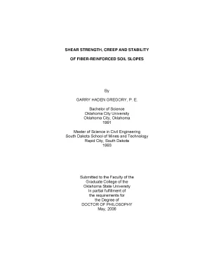
Tải xuống để đọc toàn bộSHEAR STRENGTH, CREEP AND STABILITY OF FIBER-REINFORCED SOIL SLOPES By GARRY HADEN GREGORY, P. Bachelor of Science Oklahoma City University Oklahoma City, Oklahoma 1991 Master of Science in Civil Engineering South Dakota School of Mines and Technology Rapid City, South Dakota 1993 Submitted to the Faculty of the Graduate College of the Oklahoma State University In partial fulfillment of the requirements for the Degree of DOCTOR OF PHILOSOPHY May, 2006 UMI Number: 3220239 UMI Microform 3220239 Copyright 2006 by ProQuest Information and Learning Company. All rights reserved. This microform edition is protected against unauthorized copying under Title 17, United States Code.
ProQuest Information and Learning Company 300 North Zeeb Road P. Box 1346 Ann Arbor, MI 48106-1346 SHEAR STRENGTH, CREEP AND STABILITY OF FIBER-REINFORCED SOIL SLOPES Dissertation Approved: Dr. Snethen, Advisor Dr. Todd Halihan Dr.
Gordon Emslie, Dean of the Graduate College ii ACKNOWLEDGMENTS The author wishes to gratefully acknowledge the efforts and contributions of the following individuals and firms. I sincerely appreciate the guidance, assistance, and advice provided by my advisor, Dr. Snethen, and the opportunity to have learned from his excellent teaching in the classroom and during research. I also appreciate the contributions and encouragement, provided by my other committee members, Dr.
Garold Oberlender, Dr. Stephen Cross, and Dr. Todd Halihan, and for the opportunity to have learned much in their classes. I wish to express my appreciation to Synthetic Industries of Chattanooga, Tennessee for providing the fiber material used in the research testing, and to Mr.
David Chill of Fiber Soils, Inc. for providing previous laboratory test results on fiber-reinforced soil. I want to thank Mr. David Porter who fabricated the Direct Shear Creep devices in the Civil Engineering Machine Shop.
I also appreciate the support and funding provided by the author’s firm Gregory Geotechnical and the efforts of our dedicated staff during this study, especially my daughter Marisa Duran who provided assistance during the laboratory testing program. I owe special gratitude to my wife Jan for her unwavering support, encouragement, and friendship during this effort. TABLE OF CONTENTS Chapter Page I. 1 Scope of Research Study.
2 Format of Dissertation. 9 Related Published Literature. 14 Utilization of Existing Data. 15 Effective Fiber Length.
19 FRS Shear-Strength Formulation. LABORATORY TESTING PROGRAM. 29 Laboratory Test Series. 29 Sample and Specimen Terminology.
29 Quantities and Types. 32 Bulk Sample Preparation. 32 Clay Soil Sample. 32 Silty Sand Sample.
33 Index and Classification Tests. 35 Liquid and Plastic Limits Tests. 35 Percent Passing No. 35 iv Standard Proctor Tests.
35 Sieve Analysis Tests. 36 Maximum-Minimum Index Density Tests. 36 Specimen Preparation Prior to Compaction. 36 Moisture and Weight Preparation.
38 Compaction of Clay Specimens. 40 Triaxial Shear Specimens. 40 Direct Shear Specimens. 46 Storage of Specimens.
46 Moisture Content Stability During Storage. 47 Compaction of Sand Specimens. 48 Triaxial Shear Specimens. 48 Direct Shear Specimens.
50 Triaxial Shear Tests – Clay. 51 Mounting in Triaxial Cell. 52 Saturation and Consolidation. 55 Electronic Data Acquisition.
55 Inspection and Dissection of Specimens Following Test. 56 Direct Shear Tests – Clay. 56 Mounting in Direct Shear Box. 57 Saturation and Consolidation.
59 Electronic Data Acquisition. 60 Inspection and Dissection of Specimens Following Test. 61 Creep Tests – Clay. 62 Mounting in Creep Device.
63 Saturation and Consolidation. 64 Creep Shear Stage. 65 Electronic Data Acquisition. 66 Triaxial Shear Tests – Sand.
67 Consolidation and Saturation. 68 Dissection and Inspection of Specimens Following Test. 69 v Direct Shear Tests – Sand. 69 Test Type and Shear Stage.
69 Inspection and Dissection of Specimens Following Test. 70 Interface Shear Tests. 70 Specimen Preparation and Test Observation. CORRELATION AND ANALYSIS OF DATA.
75 Triaxial Shear Test Data. 75 Available Test Data. 75 Summary of Current Triaxial Test Data. 76 Summary of Previous AGT Laboratory Triaxial Test Data.
78 Direct Shear Test Data. 80 Summary of Direct Shear Test Data. 80 Creep Test Data. 82 Interface Test Data.
85 Correlation of Shear Strength with Conceptual Model. 86 Conceptual Model Calculations. 86 Frictional Strength Correlations for Current Test Results. 87 Frictional Strength Correlations for Previous AGT Test Results.
88 Cohesive Strength Correlations for Current Test Results. 89 Cohesive Strength Correlations for Previous AGT Test Results. 90 Calibration of Conceptual Model. 91 Decay Function for Large Fiber Content.
APPLICATION OF FRS IN SLOPE STABILITY. 95 Slope Stability Analysis of FRS Slopes. 96 Analysis Using Existing Computer Programs. 96 Analysis Using Modified Computer Programs.
CASE HISTORY PROJECTS. 98 PGBT Turnpike Project. 98 FRS Application in Project. 99 Slope Stability Analyses.
100 Project Related Testing. 102 vi Lake Ridge Parkway Slope Repair Project. 102 FRS Application in Project. 103 Obtaining Soil Samples for Research Testing.
103 Project Related Testing. 104 Slope Stability Analyses. CONCLUSIONS AND RECOMMENDATIONS. 117 Conclusions Regarding Laboratory Test Results.
118 Conclusions Regarding Conceptual Model Development. 118 Conclusions Regarding Application of Model. 119 Recommendations Regarding Project Applications. 120 Recommendations for Future Research.
127 LABORATORY TEST REPORTS. 192 SCHEMATIC DRAWINGS – DIRECT SHEAR CREEP DEVICE. 195 SLOPE STABILITY ANALYSIS - COMPUTER OUTPUT. 196 vii LIST OF TABLES Table Page 1.
Routine Laboratory Testing Program. Shear Strength and Creep Laboratory Testing Program. Approximate Test Durations. Summary of Triaxial Test Results.
Summary of Triaxial Test Results (1-Specimen Tests). AGT Soil Properties. Summary of AGT Triaxial Test Results. Summary of Direct Shear Test Results.
81 viii LIST OF FIGURES Figure Page 1. FRS Mixture with Sand. Normal Stress on Planar Reinforcement. Range of Potential Orientation About Fiber Longitudinal Axis.
Stress Distribution on Fiber Cross-Sectional Axis. Effective Fiber Length Across Shear Plane. Geometry of Fiber Distribution in Sphere Space. Rotation Point of FRS Strength Envelope.
Processing of Clay Sample. Clay Specimens Prior to Hydration. Spreading Fibers over Hydrated Clay Soil Specimen. Initial Hand Mixing of FRS Specimen.
Final Hand Mixing of FRS Specimen. Mixed FRS Specimen Ready for Storage or Compaction. Placement of Loose Specimen into Mold. Compaction With Metal Rod.
Rod Plunged to Near Bottom of Mold During Initial Compaction. Finishing Compaction With Piston and Guide Ring. Preparation for Compaction of Direct Shear Specimen. 47 ix Figure Page 19.
Completing Compaction of Direct Shear Specimen. Clay Specimen Storage Cooler. Preparation of Sand Specimen in Split Mold. Addition of Fibers to Sand Specimen During Compaction.
Compacted Sand Specimen After Removal of Split Mold. Preparation of FRS Sand Specimen in Direct Shear Box. FRS Specimen Mounted on Base of Triaxial Cell. Specimen With Membrane and Top Cap in Place.
Saturation/Consolidation Stage. Shear Stage of Triaxial Test on Clay Specimen. Test Data Display in Real Time on Computer Screen. Clay Triaxial Specimen Following Test.
Dissected Triaxial Clay Specimen With Exposed Fibers. Mounting of Clay Specimen in Direct Shear Box. Computer Controlled Direct Shear Machine. Dissected Direct Shear Clay Specimen With Exposed Fibers.
Direct Shear Creep Devices. Mounting Clay Specimen in Creep Device. Fully Mounted Creep Specimen With Water in Reservoir. Triaxial Test on Sand Specimen.
Large Scale Direct Shear Machines Used in Interface Tests. Real Time Data From Interface Shear Tests. Sheet Material on Bottom Shear Box After Interface Test. Plot of Creep Test Data in Semi-Log Form.
Plot of Creep Test Data in Arithmetic Form. Interface Shear Test Results – Fiber Material on Soils. Model Versus Current Test Results for Tan Ø. Model Versus AGT Test Results for Tan Ø.
Model Prediction Versus Current Test Results for c. Model Versus AGT Test Results for c. Fiber Content Versus Reduction Factor for Interface Coefficients. Spreading Fibers for FRS on PGBT Project.
Mixing FRS on PGBT Project. Dissected Field Specimen Following Triaxial Test. Mixer for Processing Fiber-Soil Specimen into Slurry. Sieving of Slurry to Extract Fibers.
Slope Failure on Lake Ridge Parkway. Slope Failure Scarp at Roadway Edge – Lake Ridge Pkwy. Slope Failure at Roadway Edge – Lake Ridge Pkwy. 111 xi Figure Page 58.
Initial Excavation for FRS Slope Repair – Lake Ridge Pkwy. Partially Used Fiber Supply Bag – Lake Ridge Pkwy. FRS Embankment Construction – Lake Ridge Pkwy. Down Slope View of Completed FRS Embankment – Lake Ridge.
Up Slope View of Completed FRS Embankment–Lake Ridge Pkwy. 116 xii NOMENCLATURE ASTM = American Society for Testing and Materials c = cohesion of raw soil Δc frs = corrected apparent increase in cohesive strength due to fiber c frs = the cohesion value of FRS d = diameter of fiber, or equivalent diameter for non-circular fiber FRS = fiber-reinforced soil FS = factor of safety fc = interaction coefficient related to the cohesive component of the shear strength fφ = interaction coefficient related to the frictional component of the shear strength (sometimes referred to as fφ tan φ = tan δ) Gs = Specific Gravity of fiber material K 0 = At-rest earth pressure coefficient l = length of fiber Le = effective length of an individual fiber nf = average number of fibers per unit volume NP = non plastic Nf = number of fibers intersecting the shear plane pcf = pounds per cubic foot xiii Nomenclature (continued) τ frsc = uncorrected apparent increase in cohesive shear strength due to fiber τ frsφ = apparent increase in frictional shear strength due to fiber tan φ frs = tangent of the friction angle for FRS Vr = fiber volume ratio (ratio of fiber volume to total volume of a unit mass of FRS) Wf = weight of fibers in a unit volume of FRS z = depth below ground surface γ = soil unit weight γw = unit weight of water φ = angle of shearing resistance of raw soil σh or σh = horizontal stress σv or σv = vertical stress xiv CHAPTER I INTRODUCTION Background The concept of fiber-reinforced soil (FRS) dates to ancient times when clay bricks were reinforced with straw fibers. This concept is also similar to natural root reinforcement of soil where micro root structure increases the apparent shear strength of the root reinforced zone compared to similar soil with no root structure. The use of geosynthetics (synthetic plastic materials) for reinforcement of soil structures has become well established in the past 20 years.
The geosynthetic reinforcement materials initially consisted mostly of geotextiles and geogrids, often referred to as planar reinforcement. Techniques for design and analysis of earth structures reinforced with planar geosynthetics are well developed, and have been presented extensively in the literature. The rapid increase in the use of planar geosynthetics led to the concept and development of synthetic fibers for soil reinforcement. The concept of using short synthetic fibers for soil reinforcement was the subject of several early research studies and was discussed in the literature (Andersland and Khattak, 1979; Hoare, 1979; Gray and Ohashi, 1983).
However, short synthetic fibers for soil reinforcement were not commercially available until about 1990 when a pilot 1 program of fiber research, production, and full-scale test projects was undertaken by a major geosynthetics manufacturer in the United States (Synthetic Industries, 1990). The author became involved in numerous projects consisting of fiber- reinforced embankments and related laboratory testing in 1994. Fiber-reinforced soil (FRS) has been used successfully on more than 50 embankment slopes in the United States in the past 15 years (Gregory and Chill, 1998, Gregory, 1999b, Chill 2006). The author has been involved in more that 15 of the FRS projects.
The geosynthetic fiber reinforcement has consisted of 1-inch to 2.75-inch (25- to 70-mm) length polypropylene fibers. These fibers, when mixed into the soil, significantly increase the apparent shear strength of the entire soil mass. An FRS mixture is illustrated in Figure 1.
Nội dung được bảo vệ bản quyền — Tải xuống đầy đủ
Trích dẫn luận án này
Garry Haden Gregory (2006). Shear strength, creep và stability của fiber-reinforced soil slopes [Luận án tiến sĩ, Oklahoma State University]. LuanAn.net. https://luanan.net/ky-thuat-xay-dung-kien-truc/ky-thuat-xay-dung-dan-dung-cong-nghiep/shear-strength-creep-stability-fiber-reinforced-soil-slopes
Từ khóa và chủ đề nghiên cứu
Từ khóa liên quan
Xem thêm luận án cùng lĩnh vực
Chủ đề nghiên cứu
Câu hỏi thường gặp
Luận án "Shear strength, creep và stability của fiber-reinforced soil slopes" nghiên cứu về vấn đề gì?
Luận án tiến sĩ nghiên cứu độ bền cắt, creep và ổn định sườn đất tăng cường bằng sợi. Phân tích thực nghiệm, mô hình lý thuyết và ứng dụng kỹ thuật xây dựng.
Luận án "Shear strength, creep và stability của fiber-reinforced soil slopes" được bảo vệ tại trường nào?
Luận án này được bảo vệ tại Oklahoma State University. Năm bảo vệ: 2006.
Luận án "Shear strength, creep và stability của fiber-reinforced soil slopes" thuộc chuyên ngành gì?
Luận án "Shear strength, creep và stability của fiber-reinforced soil slopes" thuộc chuyên ngành Kỹ thuật Xây dựng. Danh mục: Kỹ Thuật Xây Dựng Dân Dụng & Công Nghiệp.
Luận án "Shear strength, creep và stability của fiber-reinforced soil slopes" có bao nhiêu trang?
Luận án "Shear strength, creep và stability của fiber-reinforced soil slopes" có 242 trang. Bạn có thể xem trước một phần tài liệu ngay trên trang web trước khi tải về.
Cách tải luận án "Shear strength, creep và stability của fiber-reinforced soil slopes" về máy như thế nào?
Để tải luận án về máy, bạn nhấn nút "Tải xuống ngay" trên trang này, sau đó hoàn tất thanh toán phí lưu trữ. File sẽ được tải xuống ngay sau khi thanh toán thành công. Hỗ trợ qua Zalo: 0559 297 239.