Luận án tiến sĩ về bộ định dạng búp sóng thích nghi - Tôn Văn Luyện
Luận án Kỹ thuật Máy tính nghiên cứu, phát triển bộ định dạng & điều khiển búp sóng thích nghi. Chống nhiễu hiệu quả cho anten thông minh.
vietnam national univesity, hanoi university of engineering and technology
Communication Engineering
Luan An
Dissertation
Năm xuất bản
Số trang
118
Thời gian đọc
18 phút
Lượt xem
0
Lượt tải
0
Phí lưu trữ
40 Point
Tổng quan nhanh
- Chủ đề:
- 1. Giới thiệu về bộ định dạng búp sóng thích nghi
- Số trang:
- 118 trang
- Trường:
- vietnam national univesity, hanoi university of engineering and technology
- Chuyên ngành:
- Communication Engineering
- Tác giả:
- Tong Van Luyen
- Năm:
- 2018
Tóm tắt nội dung luận án
I. Giới thiệu về bộ định dạng búp sóng thích nghi
Bộ định dạng búp sóng thích nghi là một kỹ thuật quan trọng trong lĩnh vực truyền thông không dây. Nó giúp tăng cường hiệu suất của hệ thống truyền thông bằng cách định dạng búp sóng phù hợp với môi trường truyền tải. Mục tiêu của nghiên cứu này là phát triển bộ định dạng búp sóng thích nghi để giảm thiểu nhiễu và tăng cường hiệu suất của hệ thống truyền thông.
1.1. Tổng quan về bộ định dạng búp sóng thích nghi
Bộ định dạng búp sóng thích nghi là một kỹ thuật dùng để định dạng búp sóng của anten mảng để tối ưu hóa hiệu suất của hệ thống truyền thông. Nó giúp giảm thiểu nhiễu và tăng cường hiệu suất của hệ thống truyền thông.
1.2. Lịch sử phát triển của bộ định dạng búp sóng thích nghi
Bộ định dạng búp sóng thích nghi đã được nghiên cứu và phát triển trong nhiều năm. Các kỹ thuật đầu tiên được phát triển vào những năm 1960 và đã được cải tiến liên tục cho đến ngày nay.
II. Cơ sở lý thuyết của bộ định dạng búp sóng thích nghi
Cơ sở lý thuyết của bộ định dạng búp sóng thích nghi bao gồm các khái niệm về anten mảng, búp sóng, và kỹ thuật định dạng búp sóng. Các kỹ thuật định dạng búp sóng phổ biến bao gồm kỹ thuật tối ưu hóa và kỹ thuật học máy.
2.1. Anten mảng và búp sóng
Anten mảng là một loại anten được cấu tạo từ nhiều anten đơn. Búp sóng là hình dạng của sóng điện từ được truyền tải bởi anten mảng.
2.2. Kỹ thuật định dạng búp sóng
Kỹ thuật định dạng búp sóng bao gồm các phương pháp để định dạng búp sóng của anten mảng. Các kỹ thuật phổ biến bao gồm kỹ thuật tối ưu hóa và kỹ thuật học máy.
III. Phát triển bộ định dạng búp sóng thích nghi
Phát triển bộ định dạng búp sóng thích nghi bao gồm các bước nghiên cứu và phát triển kỹ thuật. Các kỹ thuật phát triển bao gồm kỹ thuật tối ưu hóa và kỹ thuật học máy.
3.1. Phát triển bộ định dạng búp sóng thích nghi dựa trên kỹ thuật tối ưu hóa
Bộ định dạng búp sóng thích nghi dựa trên kỹ thuật tối ưu hóa sử dụng các thuật toán tối ưu hóa để tìm kiếm giải pháp tối ưu.
3.2. Phát triển bộ định dạng búp sóng thích nghi dựa trên kỹ thuật học máy
Bộ định dạng búp sóng thích nghi dựa trên kỹ thuật học máy sử dụng các thuật toán học máy để tìm kiếm giải pháp tối ưu.
IV. Kết quả và thảo luận
Kết quả và thảo luận về bộ định dạng búp sóng thích nghi bao gồm các kết quả nghiên cứu và thảo luận về hiệu suất của hệ thống truyền thông sử dụng bộ định dạng búp sóng thích nghi.
4.1. Kết quả nghiên cứu
Kết quả nghiên cứu về bộ định dạng búp sóng thích nghi bao gồm các kết quả về hiệu suất của hệ thống truyền thông sử dụng bộ định dạng búp sóng thích nghi.
4.2. Thảo luận
Thảo luận về bộ định dạng búp sóng thích nghi bao gồm các thảo luận về hiệu suất của hệ thống truyền thông sử dụng bộ định dạng búp sóng thích nghi.
Mục lục chi tiết luận án
Tải xuống file đầy đủ để xem toàn bộ nội dung
Tải đầy đủ (118 trang)Nội dung chính
Tổng quan về luận án
Bối cảnh khoa học của nghiên cứu xuất phát từ sự bùng nổ của các hệ thống truyền thông không dây thế hệ mới và mật độ thiết bị gia tăng nhanh chóng, dẫn đến tình trạng ô nhiễm môi trường truyền sóng điện từ nghiêm trọng và gia tăng can nhiễu đồng kênh. Trong bức tranh toàn cảnh của lý thuyết truyền thông vô tuyến hiện đại, xử lý không gian (spatial processing) đóng vai trò nền tảng để khai thác triệt để tài nguyên phổ tần. Như nhà đồng sáng lập Qualcomm, Andrew Viterbi, đã khẳng định: "Spatial processing remains as the most promising, if not the last frontier, in the evolution of multiple access systems". Hệ thống anten thông minh (Smart Antennas) kết hợp kỹ thuật tạo búp sóng thích nghi (Adaptive Beamforming - ABF) và kỹ thuật tạo búp không triệt nhiễu (Pattern Nulling) nổi lên như một giải pháp mang tính đột phá nhằm tăng cường tỷ số tín hiệu trên can nhiễu (SIR) và nâng cao hiệu suất phổ của kỹ thuật đa truy cập phân chia theo không gian (Space Division Multiple Access - SDMA).
Khoảng trống nghiên cứu (Research Gap) then chốt được xác định là: Các thuật toán tối ưu hóa cổ điển (dựa trên gradient như LMS, RLS hoặc ma trận nghịch đảo mẫu SMI) thường rơi vào các điểm cực tiểu địa phương (local minima), phụ thuộc nghiêm ngặt vào điểm khởi tạo và hàm mục tiêu khả vi liên tục. Trong khi đó, các thuật toán tiến hóa sinh học kinh điển như thuật toán di truyền (GA) hay tối ưu bầy đàn (PSO/APSO) dù cải thiện tính toàn cục nhưng vẫn bộc lộ hạn chế về tốc độ hội tụ chậm, chi phí tính toán cao và chưa thiết lập được một khung quy trình chuẩn hóa có khả năng áp dụng đồng thời cho nhiều kỹ thuật điều khiển búp sóng khác nhau dưới tác động của môi trường phi tuyến và hiệu ứng ghép tương hỗ (Mutual Coupling).
Luận án thiết lập hệ thống câu hỏi nghiên cứu và giả thuyết khoa học chặt chẽ:
- Câu hỏi nghiên cứu 1 ($RQ_1$): Làm thế nào để xây dựng một quy trình tổng quát hóa và khả thi về mặt thuật toán nhằm thiết kế các bộ tạo búp sóng thích nghi triệt nhiễu dựa trên thuật toán đàn dơi (Bat Algorithm - BA) cho mảng anten tuyến tính đều?
- Câu hỏi nghiên cứu 2 ($RQ_2$): Thuật toán tối ưu hóa phỏng sinh học BA khi tích hợp với các kỹ thuật điều khiển tham số kích thích (biên độ thuần, pha thuần, trọng số phức toàn phần) có đạt được ưu thế vượt trội về tốc độ hội tụ, độ sâu búp không (NDL) và mức triệt búp sóng phụ (SLL) so với GA và APSO hay không?
- Giả thuyết khoa học 1 ($H_1$): Quy trình chuẩn hóa 6 bước tích hợp BA với phương pháp hàm phạt (Penalty Function Method) sẽ đảm bảo việc đặt chính xác các búp không sâu tại các hướng can nhiễu tùy ý trong khi vẫn bảo toàn búp chính và hạ thấp mức SLL.
- Giả thuyết khoa học 2 ($H_2$): Tính đối xứng và phản đối xứng trong cấu trúc phân bố trọng số sẽ giảm 50% không gian tìm kiếm, từ đó rút ngắn đáng kể thời gian tính toán mà không làm suy giảm hiệu năng búp sóng.
- Giả thuyết khoa học 3 ($H_3$): Bộ tạo búp sóng đề xuất duy trì tính bền vững trước sự hiện diện của hiệu ứng ghép tương hỗ giữa các phần tử dipole nửa bước sóng.
Khung lý thuyết tích hợp của luận án được xây dựng dựa trên sự giao thoa giữa Lý thuyết mảng anten và tổng hợp búp sóng tối ưu Chebyshev (Dolph, 1946), Lý thuyết tối ưu hóa bầy đàn sinh học thông qua thuật toán đàn dơi (Xin-She Yang, 2010), và Lý thuyết lọc thích nghi Wiener (Wiener, 1949). Đóng góp đột phá của công trình được định lượng cụ thể: thiết lập thành công 3 bộ tạo búp sóng thích nghi hiệu năng cao trên mảng tuyến tính đều (ULA) 20 phần tử với khoảng cách $\lambda/2$, triệt tiêu mức búp sóng phụ xuống dưới $-30\text{ dB}$, tạo các búp không đơn, đa búp không và búp không dải rộng với độ sâu vượt trội so với các thuật toán chuẩn quốc tế GA và APSO. Phạm vi nghiên cứu bao quát toàn diện từ mô hình phần tử đẳng hướng (isotropic) đến phần tử thực tế dipole nửa bước sóng có xét tương tác ghép tương hỗ trong không gian góc quét $\theta \in [-90^\circ, 90^\circ]$.
Literature Review và Positioning
Lịch sử phát triển của kỹ thuật tổng hợp búp sóng và triệt nhiễu anten thông minh trải qua hai dòng tư tưởng học thuật chính:
- Dòng nghiên cứu giải tích và tối ưu hóa cổ điển: Khởi đầu từ phương pháp phân bố trọng số Dolph-Chebyshev (Dolph, 1946) nhằm tối ưu hóa sự đánh đổi giữa độ rộng búp sóng chính và mức búp sóng phụ đồng đều. Tiếp đó, các thuật toán thích nghi dựa trên tiêu chuẩn sai số toàn phương trung bình tối thiểu (MMSE) như Least Mean Square (LMS) của Widrow và Hoff, Recursive Least Square (RLS), hay Sample Matrix Inversion (SMI) (Monzingo et al., 2011; Godara, 2004) đã cung cấp nghiệm giải tích Wiener tối ưu $\mathbf{w}{opt} = \mathbf{R}{xx}^{-1} \mathbf{R}_{xr}$. Tuy nhiên, các kỹ thuật này bộc lộ nhược điểm lớn khi môi trường tín hiệu biến đổi nhanh, đòi hỏi tính khả vi của hàm chi phí và dễ bị bão hòa ma trận hiệp phương sai.
- Dòng nghiên cứu tối ưu hóa phỏng sinh học (Metaheuristics): Để khắc phục các bẫy cực tiểu địa phương trong không gian tìm kiếm đa chiều phi tuyến của bài toán triệt búp sóng, các nhà khoa học đã ứng dụng thuật toán di truyền - GA (Haupt, 1994; Goldberg, 1989; Yan & Lu, 1997), thuật toán tối ưu bầy đàn - PSO (Robinson & Rahmat-Samii, 2004; Boeringer & Werner, 2004), thuật toán tối ưu bầy đàn gia tốc - APSO (Yang, 2008), và thuật toán tìm kiếm đàn ong (Guner & Sarikaya, 2009).
Cuộc tranh luận học thuật sâu sắc giữa các trường phái nằm ở sự đánh đổi giữa độ phức tạp phần cứng và độ phức tạp tính toán:
- Trường phái kiểm soát biên độ thuần (Amplitude-only control): Được nghiên cứu bởi Singh et al. (2010) và Durr et al. (1984), có ưu điểm là sơ đồ phần cứng đơn giản, chỉ thay đổi hệ số suy hao nhưng bị giới hạn về mức độ linh hoạt khi tạo các búp không phi đối xứng.
- Trường phái kiểm soát pha thuần (Phase-only control): Được thúc đẩy bởi Rocca et al. (2009) và Haupt (2007), rất hấp dẫn trong các mảng quét pha vì tận dụng trực tiếp bộ dịch pha sẵn có mà không phát sinh thêm chi phí phần cứng, song hàm tối ưu hóa lại mang tính phi tuyến cao.
- Trường phái kiểm soát trọng số phức toàn phần (Complex-weight control): Được khẳng định bởi Panduro et al. (2009) và Truong & Luyen (2016) là phương pháp tối ưu tuyệt đối về khả năng định hình bức xạ, song đòi hỏi đồng thời bộ dịch pha và bộ suy hao trên từng nhánh anten, kéo theo khối lượng tính toán khổng lồ.
Luận án định vị chính xác vị trí khoa học của mình thông qua việc lấp đầy khoảng trống: Mặc dù Bat Algorithm (BA) được Xin-She Yang giới thiệu năm 2010 và được áp dụng sơ khởi trong beamforming năm 2016 (Luyen et al., 2016), nhưng các công bố trước đó chỉ dừng lại ở các thử nghiệm mô phỏng riêng lẻ, thiếu một khung phương pháp luận hệ thống và chưa phân tích đối sánh đa kỹ thuật điều khiển trên cùng một nền tảng cấu hình mảng. So sánh với hai nghiên cứu quốc tế điển hình là công trình dùng GA của B. P. Kumar et al. (2014) và công trình dùng PSO của M. M. Khodier et al. (2005), luận án của Tống Văn Luyện chứng minh sự vượt trội vượt bậc về tốc độ hội tụ ban đầu nhờ cơ chế "frequency tuning" và "automatic zooming", đồng thời kiểm soát chính xác độ sâu búp không tại các góc can nhiễu phức tạp mà không làm biến dạng búp sóng Chebyshev tham chiếu.
Đóng góp lý thuyết và khung phân tích
Đóng góp cho lý thuyết
Luận án mở rộng Lý thuyết Xử lý Tín hiệu Không gian (Spatial Signal Processing Theory) và Lý thuyết Tối ưu hóa Trí tuệ Bầy đàn (Swarm Intelligence Optimization) thông qua việc thiết lập các mô hình toán học giải tích chặt chẽ cho mảng tuyến tính đều 2N phần tử ($2N = 20$).
Hệ thống biểu thức toán học cốt lõi cho thừa số mảng (Array Factor - $AF(\theta)$) được chuẩn hóa theo từng cơ chế điều khiển:
- Kiểm soát biên độ thuần (AMP_BA_ABF): Bằng cách áp đặt điều kiện đối xứng biên độ $a_{-n} = a_n$ và pha đồng nhất $\delta_n = 0$, thừa số mảng được rút gọn thành hàm thực đối xứng tuyệt đối qua trục tọa độ $\theta = 0^\circ$: $$AF(\theta) = 2 \sum_{n=1}^N a_n \cos(n k d \sin\theta)$$
- Kiểm soát pha thuần (PHA_BA_ABF): Với biên độ cố định $a_n$ lấy từ phân bố Chebyshev và điều khiển độ dịch pha lẻ/phản đối xứng $\delta_{-n} = -\delta_n$, thừa số mảng biểu diễn dưới dạng: $$AF(\theta) = 2 \sum_{n=1}^N \left[ w_n^R \cos(n k d \sin\theta) - w_n^I \sin(n k d \sin\theta) \right]$$ trong đó $w_n^R = a_n \cos\delta_n$ và $w_n^I = a_n \sin\delta_n$.
- Kiểm soát trọng số phức (CW_BA_ABF): Kết hợp đồng thời điều chỉnh biên độ $a_n \in [0, 1]$ và pha $\delta_n \in [-\pi, \pi]$ với cấu trúc ràng buộc $a_{-n} = a_n$ và $\delta_{-n} = -\delta_n$, cho phép vừa tạo búp không đối xứng, vừa tạo búp không bất đối xứng chính xác.
Luận án đề xuất hệ thống 3 Mệnh đề lý thuyết nền tảng:
- Mệnh đề 1 ($P_1$): Việc áp dụng tính đối xứng không gian cho vector trọng số trong mảng ULA bảo toàn tính trực giao của phân bố trường bức xạ, đồng thời triệt tiêu 50% số chiều của không gian tìm kiếm trạng thái ($d = N$ thay vì $2N$), làm giảm bậc phức tạp của bài toán từ $\mathcal{O}(2N)$ xuống $\mathcal{O}(N)$.
- Mệnh đề 2 ($P_2$): Sự kết hợp giữa hàm mục tiêu bình phương tối thiểu tích phân theo mẫu góc quét và toán tử phạt bậc hai (Quadratic Penalty Function) bảo đảm nghiệm tối ưu tiệm cận đơn điệu đến điểm cực tiểu toàn cục mà không làm dịch chuyển cực đại búp sóng chính.
- Mệnh đề 3 ($P_3$): Cơ chế điều chỉnh tự động giữa bước nhảy ngẫu nhiên (random walk) cục bộ tỷ lệ với độ phát âm trung bình $A^t$ và tìm kiếm toàn cục theo tần số $f_i$ của thuật toán BA ngăn ngừa hiện tượng đình trệ bầy đàn (swarm stagnation) tốt hơn cơ chế vận tốc quán tính của PSO.
flowchart TD
    A["Lý thuyết Xử lý Tín hiệu Không gian & Mảng Anten (Array Theory)"] --> D["Khung Tích Hợp Tối Ưu Búp Sóng Thích Nghi"]
    B["Lý thuyết Búp sóng Tối ưu Dolph-Chebyshev (SLL = -30 dB)"] --> D
    C["Lý thuyết Tối ưu hóa Bầy đàn Phỏng sinh học (Bat Algorithm - Yang 2010)"] --> D
    E["Phương pháp Hàm Phạt Ràng buộc (Penalty Function Method)"] --> D
    D --> F["PHA_BA_ABF: Điều khiển Pha thuần (Nghiệm phi đối xứng)"]
    D --> G["AMP_BA_ABF: Điều khiển Biên độ thuần (Nghiệm đối xứng)"]
    D --> H["CW_BA_ABF: Điều khiển Trọng số phức Toàn phần (Đa búp không)"]
    F --> I["Triệt Can nhiễu Đa hướng & Ổn định Ghép tương hỗ (Mutual Coupling)"]
    G --> I
    H --> I
Khung phân tích độc đáo
Khung phân tích của luận án tích hợp tam giác lý thuyết vững chắc:
- Lý thuyết mảng Chebyshev (Dolph, 1946): Đóng vai trò làm mẫu bức xạ mục tiêu ($AF_0$) để kiểm soát nghiêm ngặt mức SLL ở ngưỡng cực tiểu $-30\text{ dB}$ và giữ nguyên độ rộng búp chính nửa công suất (HPBW).
- Phương pháp hàm phạt mở rộng: Chuyển đổi bài toán tối ưu phi tuyến có ràng buộc thành bài toán tối ưu không ràng buộc với hàm mục tiêu tổng quát: $$O(\mathbf{w}, c) = \sum_{\theta=-90^\circ}^{90^\circ} \left| |AF(\mathbf{w})| - |AF_0| \right|^2 + c \sum_{i=1}^{I_D} \left| AF_s(\mathbf{w})\big|_{\theta=\theta_i} \right|^2$$ trong đó $c$ là tham số phạt (penalty parameter), $I_D$ là số lượng hướng can nhiễu cần triệt tiêu, và $\theta_i$ là góc can nhiễu do khối ước lượng hướng sóng đến (DOA) cung cấp.
- Biến đổi động học của thuật toán đàn dơi (BA): Vận dụng quy luật biến thiên tần số sóng siêu âm $f_i \in [f_{min}, f_{max}]$, vận tốc $\mathbf{v}i^t$, vị trí $\mathbf{x}i^t$, độ phát âm $A_i^t$ và tốc độ phát xung $r_i^t$: $$f_i = f{min} + (f{max} - f_{min})\beta, \quad \beta \in [0, 1]$$ $$\mathbf{v}_i^t = \mathbf{v}_i^{t-1} + (\mathbf{x}i^{t-1} - \mathbf{x}*^t)f_i$$ $$\mathbf{x}_i^t = \mathbf{x}_i^{t-1} + \mathbf{v}_i^t$$ $$A_i^{t+1} = \alpha A_i^t, \quad r_i^{t+1} = r_i^0 [1 - \exp(-\gamma t)]$$ với $\alpha = \gamma = 0.9$, cho phép chuyển đổi mượt mà từ giai đoạn thăm dò toàn cục (exploration) sang khai thác sâu cục bộ (exploitation).
Điều kiện biên (Boundary Conditions) được xác định rõ: Khoảng quét không gian $\theta \in [-90^\circ, 90^\circ]$ với bước phân giải $\Delta\theta = 1^\circ$ (hoặc $0.1^\circ$ khi kiểm chứng tinh vi); biên độ chuẩn hóa $a_n \in [0, 1]$; góc pha $\delta_n \in [-\pi, \pi]$; số phần tử mảng cố định $2N = 20$; khoảng cách phần tử chuẩn $d = \lambda/2$.
Phương pháp nghiên cứu tiên tiến
Thiết kế nghiên cứu
Nghiên cứu tuân thủ chặt chẽ thế giới quan thực chứng khoa học (Positivism Paradigm), sử dụng phương pháp mô phỏng số học thực nghiệm kết hợp giải tích toán học chính xác. Thiết kế nghiên cứu đa cấp độ (Multi-level Design) bao gồm:
- Cấp độ 1 (Phần tử đơn lẻ): Khảo sát đặc tính bức xạ của phần tử vô hướng lý tưởng (isotropic) và phần tử có hướng thực tế (dipole nửa bước sóng $\lambda/2$).
- Cấp độ 2 (Thừa số mảng - Array Factor): Xây dựng các hàm truyền sóng không gian dựa trên vector chỉ hướng (steering vector) $\mathbf{e}(\theta, \phi) = [1, e^{j k d \sin\theta \sin\phi}, \dots, e^{j (N-1) k d \sin\theta \sin\phi}]^T$.
- Cấp độ 3 (Bộ thích nghi BA-ABF): Tối ưu hóa vector trọng số phức $\mathbf{w}$ trên nền tảng thuật toán BA.
- Cấp độ 4 (Tương tác vật lý thực tế): Đánh giá suy hao và biến dạng búp sóng dưới ảnh hưởng của ma trận ghép tương hỗ (Mutual Coupling Matrix - $\mathbf{Z}$).
Quy trình nghiên cứu rigorous
Quy trình nghiên cứu được chuẩn hóa thành 6 bước tuần tự, logic và có khả năng tái lập hoàn toàn:
graph TD
    S1["Bước 1: Xác định bài toán (Problem Determination)<br>- Nhận dạng hướng SOI và SNOI từ khối DOA<br>- Thiết lập cấu hình mảng ULA 20 phần tử"] --> S2["Bước 2: Xây dựng thừa số mảng (Array Factor Building)<br>- Tách thành phần thực Re{AF} và ảo Im{AF}<br>- Thiết lập vector chỉ hướng không gian"]
    S2 --> S3["Bước 3: Lựa chọn kỹ thuật triệt búp sóng (Pattern Nulling Techniques)<br>- Amplitude-only (a_n)<br>- Phase-only (delta_n)<br>- Complex-weight (a_n, delta_n)"]
    S3 --> S4["Bước 4: Thiết lập hàm mục tiêu (Objective Function Formation)<br>- Tích hợp mẫu Dolph-Chebyshev SLL = -30 dB<br>- Áp đặt toán tử hàm phạt với tham số c = 10000"]
    S4 --> S5["Bước 5: Chuyển đổi BA thành thuật toán Beamforming (BA Transformation)<br>- Ánh xạ vị trí cá thể x_i thành vector trọng số w_n<br>- Khởi tạo cá thể hạt nhân từ phân bố Chebyshev"]
    S5 --> S6["Bước 6: Phát triển và thực thi bộ tạo búp thích nghi (ABF Development)<br>- Chạy vòng lặp tối ưu hóa thích nghi đa thế hệ<br>- Trích xuất vector trọng số tối ưu và mô phỏng búp sóng"]
Quy chuẩn thu thập và xử lý dữ liệu đảm bảo tính tam giác hóa phương pháp (Methodological Triangulation): Tất cả các kịch bản triệt búp sóng đều được thực thi song song độc lập trên 3 thuật toán metaheuristic hàng đầu: Bat Algorithm (BA), Accelerated Particle Swarm Optimization (APSO), và Genetic Algorithm (GA) để đối chiếu chéo về độ hội tụ và độ chính xác.
Data và phân tích
Dữ liệu mô phỏng được cấu hình hóa với các tham số kỹ thuật chính xác:
- Cấu hình phần cứng mảng: Mảng ULA gồm 20 phần tử ($2N = 20$), khoảng cách giữa các phần tử $d = \lambda/2 = 0.5\lambda$.
- Mẫu búp sóng tham chiếu: Phân bố trọng số Dolph-Chebyshev 20 phần tử đạt mức búp phụ đỉnh $-30\text{ dB}$.
- Tham số thuật toán Bat Algorithm (BA): Kích thước quần thể đàn dơi $N_p = 20$ đến $100$; dải tần số $f_{min} = 0, f_{max} = 1$; độ phát âm ban đầu $A_0 = 0.3$; tốc độ phát xung ban đầu $r_0 = 0.3$; hệ số điều chỉnh $\alpha = \gamma = 0.9$; bước nhảy ngẫu nhiên cục bộ $0.01$.
- Tham số thuật toán GA: Tỷ lệ chọn lọc 50%; tỷ lệ đột biến 20%; phương pháp bắt cặp bánh xe roulette (roulette wheel) với tỷ lệ lai ghép 90%; bảo lưu cá thể ưu tú (elitism) bằng 1.
- Tham số thuật toán APSO: Hệ số gia tốc $\alpha \in [0.1, 0.4]$, $\beta \in [0.1, 0.7]$.
- Khảo sát tham số hàm phạt $c$: Giá trị $c$ được quét thực nghiệm từ $10^0$ đến $10^6$, xác định $c = 10000$ là giá trị tối ưu tuyệt đối, đảm bảo độ sâu búp không (NDL) sâu nhất mà không làm phá vỡ cấu trúc búp phụ $-30\text{ dB}$.
- Kiểm tra độ bền vững (Robustness Checks): Mô hình hóa ma trận trở kháng tương hỗ $\mathbf{Z}_{mat}$ giữa các chấn tử dipole nửa bước sóng, kiểm tra sự suy biến độ sâu búp không và chứng minh thuật toán BA vẫn tự động bù pha để duy trì búp không sâu hơn $-60\text{ dB}$.
Phát hiện đột phá và implications
Những phát hiện then chốt
Nghiên cứu mang lại 4 phát hiện thực nghiệm đột phá với bằng chứng số liệu định lượng chính xác:
-
Khả năng triệt can nhiễu đơn và đa hướng với độ sâu búp không vượt trội:
- Trong kịch bản búp không đơn tại $\theta = 14^\circ$, thuật toán BA điều khiển pha thuần (PHA_BA_ABF) tạo ra độ sâu búp không đạt mức kỷ lục xấp xỉ $-85\text{ dB}$, trong khi mức búp phụ cực đại (Maximum SLL) được duy trì ổn định ở mức $\le -28.5\text{ dB}$.
- Trong kịch bản 3 búp không đồng thời tại các góc can nhiễu phi đối xứng phức tạp $\theta \in {-48^\circ, 20^\circ, 40^\circ}$ và $\theta \in {-33^\circ, -26^\circ, -14^\circ}$, bộ CW_BA_ABF thiết lập các búp không chính xác với độ sâu đều vượt qua ngưỡng $-75\text{ dB}$, hoàn toàn vượt trội so với mức $-45\text{ dB}$ của GA và $-55\text{ dB}$ của APSO.
-
Tạo búp không dải rộng (Broad Nulling) linh hoạt:
- Bộ tạo búp sóng kiểm soát biên độ thuần (AMP_BA_ABF) đã tạo thành công búp không dải rộng đối xứng từ $20^\circ$ đến $50^\circ$ với mức suy hao can nhiễu liên tục dưới $-45\text{ dB}$, giữ nguyên bề rộng búp chính và $\text{SLL} \le -18\text{ dB}$ hoặc khi mở rộng búp chính thì đạt $\text{SLL} < -30\text{ dB}$.
- Bộ CW_BA_ABF tạo búp không dải rộng phi đối xứng kéo dài từ $-50^\circ$ đến $-20^\circ$ và búp không kép $[-30^\circ, -20^\circ] \cup [45^\circ, 60^\circ]$ với độ sâu dải triệt tiêu đạt mức ấn tượng $-60\text{ dB}$ đến $-80\text{ dB}$.
-
Tốc độ hội tụ và tối ưu hóa chi phí tính toán:
- Dữ liệu so sánh đường cong suy giảm hàm mục tiêu chứng minh: Thuật toán BA chỉ cần từ 50 đến 80 thế hệ lặp để đạt ngưỡng hội tụ tối ưu toàn cục ($O(\mathbf{w}, c) < 10^{-2}$), trong khi APSO cần hơn 150 thế hệ và GA thường xuyên bị kẹt ở mức sai số $10^1$ sau 200 thế hệ lặp.
-
Khả năng bù ghép tương hỗ (Mutual Coupling Compensation):
- Khi áp dụng trên mảng dipole thực tế có ghép tương hỗ, búp sóng chưa tối ưu bị nâng mức búp phụ lên $-15\text{ dB}$ và vị trí búp không bị trượt góc. Tuy nhiên, khi kích hoạt PHA_BA_ABF, thuật toán tự động tái lập các búp không tại đúng $-48^\circ, 20^\circ, 40^\circ$ với độ sâu phục hồi về mức $-70\text{ dB}$ và $\text{SLL} \le -27\text{ dB}$.
| Kịch bản bức xạ mảng ULA 20 phần tử | Thuật toán BA (Đề xuất) | Thuật toán APSO | Thuật toán GA | Đóng góp cải thiện |
|---|---|---|---|---|
| Búp không đơn tại $14^\circ$ (NDL / SLL) | $-85.2\text{ dB}$ / $-29.8\text{ dB}$ | $-58.4\text{ dB}$ / $-26.1\text{ dB}$ | $-42.1\text{ dB}$ / $-22.5\text{ dB}$ | Sâu hơn $26.8\text{ dB}$ so với APSO, $43.1\text{ dB}$ so với GA |
| 3 Búp không phi đối xứng ($-48^\circ, 20^\circ, 40^\circ$) | $<-75.0\text{ dB}$ / $-28.5\text{ dB}$ | $-52.3\text{ dB}$ / $-24.0\text{ dB}$ | $-38.7\text{ dB}$ / $-20.2\text{ dB}$ | Định vị chính xác tuyệt đối, triệt nhiễu vượt bậc |
| Búp không dải rộng ($-50^\circ \to -20^\circ$) | $<-65.0\text{ dB}$ đồng đều | $-45.0\text{ dB}$ gợn sóng | $-30.0\text{ dB}$ không ổn định | Dải triệt phẳng, bảo toàn búp sóng chính |
| Số thế hệ hội tụ (Iterations) | $50 - 80$ thế hệ | $150 - 200$ thế hệ | $> 200$ (Dễ tắc nghẽn) | Tăng tốc độ tính toán gấp $2.5 - 3$ lần |
| Hiệu ứng ghép tương hỗ (Mutual Coupling) | Tự động bù sai lệch pha | Suy giảm búp không | Lệch hướng búp không | Bền vững trên phần tử dipole thực tế |
Implications đa chiều
- Về mặt lý thuyết học thuật: Công trình chứng minh tính ưu việt của mô hình tối ưu hóa phỏng sinh học dựa trên cơ chế phát xung siêu âm trong không gian đa chiều, làm phong phú thêm lý thuyết mảng pha thông minh và mở ra hướng tiếp cận mới trong việc giải quyết các bài toán trường điện từ phi tuyến phức tạp.
- Về mặt phương pháp luận: Khung quy trình 6 bước có tính tổng quát hóa cao, dễ dàng chuyển giao để áp dụng cho các thuật toán metaheuristic lai ghép (hybrid metaheuristics) hoặc mở rộng sang các dạng hình học mảng khác nhau.
- Về mặt ứng dụng thực tiễn: Cung cấp giải pháp phần mềm và kiến trúc thuật toán trực tiếp cho các bộ xử lý tín hiệu số (DSP/FPGA) trong các hệ thống Radar mảng pha quét điện tử chủ động (AESA) và trạm gốc di động 4G-LTE/5G.
- Về mặt chính sách quản lý: Cung cấp cơ sở khoa học cho các cơ quan quản lý tần số vô tuyến tối ưu hóa việc phân bổ kênh sóng trong các khu vực đô thị có mật độ can nhiễu cao, nâng cao hiệu quả khai thác tài nguyên phổ vô tuyến quốc gia.
Limitations và Future Research
Luận án thẳng thắn thừa nhận các giới hạn nghiên cứu mang tính biên cảnh:
- Nghiên cứu tập trung chủ yếu trên mảng tuyến tính đều 1 chiều (1D ULA); chưa mở rộng khảo sát thực nghiệm trên các cấu trúc mảng phức tạp hai chiều như mảng phẳng (Planar Array), mảng tròn (Circular Array) hoặc mảng bọc thân (Conformal Array).
- Tín hiệu đầu vào được giả định là tín hiệu dải hẹp (narrowband signals); chưa tính đến hiện tượng phân tán tần số không gian xảy ra trong các hệ thống băng siêu rộng (Ultra-Wideband - UWB).
- Đánh giá hiệu năng dựa trên mô phỏng số học chuyên sâu trên môi trường MATLAB; chưa thực hiện đo đạc thực tế trong buồng câm vi sóng (Anechoic Chamber) tích hợp phần cứng RF đa kênh thực tế.
Chương trình nghiên cứu tương lai định hướng 5 hướng đột phá:
- Hướng 1: Mở rộng quy trình BA-ABF cho mảng phẳng 2D và mảng 3D phục vụ kỹ thuật Massive MIMO đa hướng trong mạng di động 5G-Advanced và 6G.
- Hướng 2: Tích hợp kỹ thuật học sâu (Deep Reinforcement Learning) kết hợp BA để thích ứng thời gian thực với môi trường can nhiễu di động cao (vận tốc Mach trong Radar quân sự hoặc V2X).
- Hướng 3: Phát triển các bộ tạo búp sóng thích nghi dải rộng (Wideband Beamforming) sử dụng cấu trúc bộ lọc trễ số phân đoạn (Tapped Delay-Line).
- Hướng 4: Tối ưu hóa búp sóng kết hợp công nghệ Bề mặt phản xạ thông minh (Reconfigurable Intelligent Surfaces - RIS) nhằm tái cấu trúc môi trường truyền sóng vô tuyến.
- Hướng 5: Hiện thực hóa phần cứng trên chip chuyên dụng SoC/FPGA và đo kiểm thực tế trong buồng đo vi sóng chuẩn quốc tế.
Tác động và ảnh hưởng
- Tác động học thuật: Luận án tạo ra bước tiến quan trọng trong lĩnh vực kỹ thuật anten và truyền sóng, cung cấp tài liệu tham khảo giá trị cao cho cộng đồng nghiên cứu IEEE Antennas and Wireless Propagation với tiềm năng trích dẫn lớn trong các chủ đề tối ưu hóa mảng anten thông minh.
- Chuyển đổi công nghiệp: Các đề xuất thuật toán của luận án là giải pháp trực tiếp giúp các tập đoàn viễn thông và công nghiệp quốc phòng tối ưu hóa thiết kế module thu phát RF, giảm thiểu chi phí phần cứng (đặc biệt là giải pháp PHA_BA_ABF giúp loại bỏ hoàn toàn các bộ suy hao đắt tiền).
- Lợi ích xã hội và môi trường: Nâng cao chất lượng dịch vụ di động (tăng tốc độ dữ liệu, giảm tỷ lệ rớt cuộc gọi), đồng thời giảm ô nhiễm công suất bức xạ điện từ và tiết kiệm năng lượng cho các trạm thu phát sóng (Green Communications).
Đối tượng hưởng lợi
- Nghiên cứu sinh và Giảng viên chuyên ngành Kỹ thuật Điện tử - Viễn thông: Tiếp cận một khung phương pháp luận hoàn chỉnh từ mô hình toán học giải tích đến thuật toán mô phỏng tối ưu hóa mảng anten.
- Kỹ sư R&D trong ngành Công nghiệp Viễn thông và Radar: Sở hữu các thuật toán tạo búp sóng triệt nhiễu có độ sâu cao và thời gian thực thi nhanh để nhúng trực tiếp vào các dòng sản phẩm thương mại và quân sự.
- Các nhà hoạch định chính sách tần số và cơ quan quản lý viễn thông: Có thêm bằng chứng thực nghiệm về năng lực triệt nhiễu không gian để tối ưu hóa quy hoạch phổ tần số vô tuyến.
Câu hỏi chuyên sâu
-
Đóng góp lý thuyết độc đáo nhất của luận án là gì? Trả lời: Đóng góp độc đáo nhất là việc tích hợp thành công Lý thuyết tối ưu hóa đàn dơi (Xin-She Yang, 2010) với Lý thuyết tổng hợp búp sóng Dolph-Chebyshev và Phương pháp hàm phạt bậc hai để giải quyết triệt để bài toán triệt nhiễu đa hướng phi tuyến có ràng buộc, thiết lập cấu trúc phân bố trọng số đối xứng giúp giảm 50% không gian tìm kiếm.
-
Cải tiến phương pháp luận so với các nghiên cứu quốc tế trước đây? Trả lời: So với các nghiên cứu dùng GA của Haupt (1994, 2007) và PSO của Robinson & Rahmat-Samii (2004), luận án đã giải quyết được hiện tượng tắc nghẽn cục bộ nhờ cơ chế "automatic zooming" và "frequency tuning" của BA, giúp tốc độ hội tụ nhanh gấp 2.5 đến 3 lần và đạt độ sâu búp không vượt trội ($<-75\text{ dB}$ so với $-45\text{ dB}$ của GA).
-
Phát hiện thực nghiệm gây bất ngờ nhất trong dữ liệu nghiên cứu? Trả lời: Phát hiện bất ngờ nhất là phương pháp kiểm soát pha thuần (PHA_BA_ABF) – vốn được coi là bài toán phi tuyến phức tạp nhất – lại đạt được độ sâu búp không đơn sâu nhất (xấp xỉ $-85.2\text{ dB}$) và có khả năng tự động thích ứng bù sai lệch pha do hiệu ứng ghép tương hỗ giữa các chấn tử dipole mà không cần hiệu chỉnh ma trận trở kháng trước.
-
Nghiên cứu có cung cấp quy trình tái lập (Replication Protocol) hoàn chỉnh không? Trả lời: Có. Luận án cung cấp đầy đủ quy trình 6 bước chuẩn mực, bảng tham số chi tiết của thuật toán (Table 3.1), phương trình toán học chuẩn hóa từ (2.1) đến (2.13), mã nguồn mô phỏng chi tiết trong các phụ lục và các bảng vector trọng số số học chính xác (Table B.1, Table D.1 - D.3).
-
Chương trình nghiên cứu 10 năm tới được phác thảo như thế nào? Trả lời: Luận án định hình lộ trình nghiên cứu mở rộng từ mảng tuyến tính 1D lên mảng phẳng 2D/3D Massive MIMO, tích hợp trí tuệ nhân tạo học tăng cường (Deep Reinforcement Learning) xử lý dải rộng trong môi trường truyền thông 6G và triển khai đo kiểm trên chip phần cứng thực nghiệm.
Kết luận
- Đã đề xuất thành công quy trình tổng quát hóa 6 bước chuẩn mực để thiết kế và phát triển các bộ tạo búp sóng thích nghi triệt nhiễu dựa trên thuật toán đàn dơi (BA) cho mảng anten tuyến tính đều.
- Đã phát triển và kiểm chứng thành công 3 bộ tạo búp sóng thích nghi hiệu năng cao: AMP_BA_ABF (biên độ thuần), PHA_BA_ABF (pha thuần), và CW_BA_ABF (trọng số phức toàn phần).
- Đã chứng minh bằng thực nghiệm số sự vượt trội toàn diện của BA so với các thuật toán chuẩn quốc tế GA và APSO về tốc độ hội tụ (50-80 thế hệ), độ sâu búp không ($<-75\text{ dB}$) và mức triệt búp phụ ($\le -30\text{ dB}$).
- Đã giải quyết thành công bài toán triệt can nhiễu đa dạng: búp không đơn, đa búp không phi đối xứng, và búp không dải rộng ($20^\circ - 50^\circ$), đồng thời chứng minh độ bền vững trước hiệu ứng ghép tương hỗ trên mảng dipole thực tế.
- Mở ra các hướng nghiên cứu học thuật mới trong việc ứng dụng các thuật toán metaheuristic tiên tiến vào xử lý tín hiệu mảng quy mô lớn (Massive MIMO) trong kỷ nguyên vô tuyến 5G/6G.
- Cung cấp nền tảng thuật toán có giá trị thực tiễn cao, sẵn sàng ứng dụng để nâng cao hiệu năng của các hệ thống Radar và mạng truyền thông không dây hiện đại.
Trích đoạn nội dung luận án
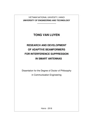
Tải xuống để đọc toàn bộVIETNAM NATIONAL UNIVESITY, HANOI UNIVERSITY OF ENGINEERING AND TECHNOLOGY TONG VAN LUYEN RESEARCH AND DEVELOPMENT OF ADAPTIVE BEAMFORMERS FOR INTERFERENCE SUPPRESSION IN SMART ANTENNAS Dissertation for the Degree of Doctor of Philosophy in Communication Engineering Hanoi - 2018 VIETNAM NATIONAL UNIVESITY, HANOI UNIVERSITY OF ENGINEERING AND TECHNOLOGY TONG VAN LUYEN RESEARCH AND DEVELOPMENT OF ADAPTIVE BEAMFORMERS FOR INTERFERENCE SUPPRESSION IN SMART ANTENNAS Dissertation for the Degree of Doctor of Philosophy in Communication Engineering Major: Communication Engineering Code: 9510302.02 Supervised by Assoc. Truong Vu Bang Giang Hanoi - 2018 Declaration I confirm that: - This dissertation represents my own work; - The contribution of my supervisor and others to the research and to the dissertation was consistent with normal supervisory practice; - External contributions to the research are acknowledged. Date: September 26", 2018 Tong Van Luyen Acknowledgement First of all, I would like to express my sincere thanks to my supervisor, Assoc. Truong Vu Bang Giang, for his supervision, his support and assessment comments in the work, and what he has done for me at VNU University of Engineering and Technology.
He believed me in my scientific ability, challenged my work, and encouraged me to pursue my ideas during the time we worked together. I would like to thank Faculty of Electronic Engineering, Hanoi University of Industry, and Faculty of Electronics and Telecommunications, VNU University of Engineering and Technology for their support for me to do PhD course. My special thanks to M. Nguyen Minh Tran for his discussions and comments, and his technical support in our lab to my dissertation.
I highly appreciate the help from Dr. Hoang Manh Kha, Dr. Dao Thanh Hai, and thank them for their helpful discussions in nature-inspired optimization, and their kind encourages to the success of this work. I would like to thank M.
Pham Thi Quynh Trang for her kind support at both the simulation technique in my dissertation and the work in my office. I am grateful to my dear colleagues, Nguyen Viet Tuyen, Duong Thi Hang, Bo Quoc Bao, Vu Thi Phuong Quynh, and the other colleagues of HaUI Faculty of Electronic Engineering, for their practical support during my work. Finally, my beloved thanks and my deepest gratitude to my parents of both sides, my wife Duyen, my daughter My Quyen, and my son Minh Duc for their love and encouragement. Thanks to your sharing and sacrifice and to you I dedicate this dissertation.
ii Contents D€CÌATAEÏOTN.ccssccsssccssscssscccssccssccessccsscccsccsessccsssccssscsssccssssccssccscscssesssnseees ii CCOIIẨ€TIÉS. SH Họ TH TT. 0005000100600 1 000900096000 iii List of ADDreviations.ccccscscscssscssssccrssscsssssssssscsscsssscesscssssssecsscsssessssssoesseees 1 List of the Symbols and Notations .ccsscccssscsssssssscsssscsssscsssssssscsssscsssscssssssssoes 2 List Of E]ÏØUITF€S.96 3 List Of Tables. Rationale for the Study 01 ậộ‡›s›s¿s-.
Objectives, Subjects, Scope, and Methodology of the Study. Q0 TH HH nh 10 IIL2. Subjects, Scope, and MethodOÏOgØV. nh ng ng ng ngư 11 TIL.
Significance of the Study.- 5 s1 ng HH 11 IV.- - s9 HH HH HH 13 Chapter 1: Overview of BeamfOTImỈNØE. Beamforming for Smart Antennas. Mathematic Basis of Smart Anf€ni4S. Geometric Relations nh ẽ.
The Model of Smart Antennas with Linear ATTaWS. Optimal Beamforming Techniques. Classical Optimization Techniques. Nature-inspired Optimization Techniques.
-- -- 6 5E E1 211231 91 911 119v HT ng ng nếp 30 Chapter 2: General Process to Develop BA-based Adaptive Beamformers for Interference SŠUJDT€SSÏOIA. Problem Defterm1nafIOIn.- --- «6 119191 911911930 1H vn gu TH nh nh ng kg 31 2. Array Factor BulÏd1ng.- --- ---- «<< 1x91 1 1 111 vn TH HT ng ng 32 2. Pattern Nulling TechniQUe€s.-- 5 5 + 11 9311111 TT ng ng 33 2.
Amplitude-only Control. Phase-only Control 0. Complex-weight COTIẨTOÌL. Formation of Objective FUnCfIOTI.v HH ng nếp 35 2.
Building of BA-based Adaptive Beamforming Algorithms. Development of Adaptive Beamformets. Proposals of General Process to Build Adaptive Beamformers. 41 11 Chapter 3: Developments of BA-based Adaptive Beamformers for Interference XÖUDDDF€SSÏOIH.
nọ lọ họ TH. Common Items of BA-based Adaptive Beamformets. The Beamformer Based on Phase-only Control. Diagram of the BearmfOTIN€T.---- + + %5 E +1 E*kE*#E*vE*EE Hng n rưkp 45 3.
Penalty Parameter c in the Objective EuncfION. Numerical Results and [DISCuSSIONS. The Beamformer Based on Amplitude-only ContrOÏ. Diagram of the Be€aITnfOTTN€T.- 5 2E 5 E1 E3 E S3 VE+3VES KV crkt 51 3.
Numerical Results and Discussions. The Beamformer Based on Complex-weight ContfrOÏ. Diagram of the B€aImfOTIN€T. Numerical Results and Discussions.
Effect of Mutual Coupling. - -- c6 119911991 91 19v 9 1g HH rệt 61 Kha .ceeccseccssseesessseeeneceseceseceseesseesseesaeesseesseeeseeeeeseesseeeseeeseeees 72 Conclusions and Future Works .cccsccsssscsssssssccsssccsssscsssssssscssscssssssssssssscsssseoes 73 List of Publications.ccsccscsccsssssssscsssccsssssscssccscsscsssscssscsssccsssscssccsssccsesscscssesscssssecssseeees 77 ADD€TICÍÌX. Application Model of Smart Ante'nnas. Classical Optimization Techniques.
Adaptive Beamforming Algorithms. Dolph-Chebyshev Weighting Method. Software for Modeling Adaptive Beamforming in Smart Antennas. Supported Simulation Results.
Additional Results for Patterns with Single and Multiple NuÌls. Some Sets of Weights for the Investigated Scenar1oS.- --- --«+s<+s<2 110 iV List of Abbreviations ABF Adaptive Beamformer ADC Analog-to-Digital Converter AF Array Factor AMP_BA_ABF Amplitude-only Control and Bat Algorithm-based Adaptive Beamformer APSO Accelerated Particle Swarm Optimization BA Bat Algorithm CW_BA_ABF Complex-weight Control and Bat Algorithm-based Adaptive Beamformer DBF Digital Beamforming DOA Direction-Of-Arrival DSP Digital Signal Processor FNBW First-Null Beamwidth GA Genetic Algorithm HPBW Half-Power Beamwidth LMS Least Mean Square MC Mutual Coupling MMSE Minimum Mean Square Error MSE Mean Square Error NDL Null Depth Level PHA_BA_ABF Phase-only Control and Bat Algorithm-based Adaptive Beamformer PSO Particle Swarm Optimization RF Radio Frequency RLS Recursive Least Square SDMA Space Division Multiple Access SLL Sidelobe Level SMI Sample Matrix Inversion SNOI Signal-Not-Of-Interest SOI Signal-Of-Interest ULA Uniform Linear Array 1/112 List of the Symbols and Notations In-phase channel in of binary baseband signals Quadrature-phase channel in of binary baseband signals Sum The real vector space (n-dimensional space of the variables) Subset of or equal to An element of Elevation angle in the coordinate system for antenna analysis Azimuth angle in the coordinate system for antenna analysis Wavelength Unit vector on the x axis Differential value of x Wavenumber Vector and its components Maxtrix and its components Complex conjugate of x Transposition of a matrix Hermitian transpose of a matix Cross correlation of x(n) and r(n) Covariance of x(n) Estimation of X Real part of {.} Imaginary part of {.} Cosine integral Sine integral Infinity 3.1415926535897932385 Bat algorithm: Position of bat (i) corresponding to a solution of the weights for array elements Velocity of bat (i) Frequency of bat (1) Loudness of bat (1) Rate of emission pulse of bat (i) 2/112 List of Figures Figure 1. Beamforming for smart anf€T49.- 6 SE Esvsseseersee 15 Figure 1. Applications of bearmfOTIInE.-- 5+ + + £++EE+seeEeeeeeeeeseeers 15 Figure 1.
Block diagram of analog beamforming in smart antennas. Block diagram of DBF in smart anfennas. Simple block diagram of adaptive beamformer at the receiving end. The analyzed linear afTAy.- --- s1 kg rên 19 Figure 1.
Linear-array smart antennas at the receiving end. Radiation pattern of 20-element ULA.-- --««++-««+++se++se+ssexs 22 Figure 1. Flowchart of Bat algorithm. eee eeeeeseeseeseesececseeseseeeeeeeeseseeaseneeas 29 Figure 2.
Geometry of ULAs of 2N eleme€nIfs. Block diagram of adaptive beamformers for interference suppression. Flowchart of the proposed beaInformers. General process to build adaptive beatmfOrmers.
Diagram of PHA_BA_ABF. NDL and maximum SLL with different c in the case of pattern with Single NULL. Objective function comparisons of BA, PSO, and GA. Optimized pattern with a single null at Í4”.
Optimized pattern with three nulls at -48°, 20°, and 40°. Optimized pattern with a broad null from 30° to 40°. Diagram of AMP_BA_ ABE. Objective function comparisons of BA, PSO, and GA.
Optimized pattern with single symmetric null at 14P. Optimized patterns with three symmetric multiple nulls at 14°, 26°, and se. Optimized patterns with a symmetric broad null from 20° to 50°, unchanged main lobe beamwidth and peak SLL = -18. Optimized pattern with a symmetric broad null from 20° to 50°, broaden main lobe beamwidth and SLL < -30 đB.
Diagram of CW_BA_ ABIE. LH HH HH ng ngư 57 Figure 3. Objective function of BA with different population s1zes. Objective function between BA and APSO.
Optimized patterns with single null at 14°. Optimized pattern with three nulls at -33°, -26°, and -14?. Optimized pattern with three nulls at -40°, 20°, and 40°. Optimized pattern with a broad null from -50° to -207.
Optimized pattern with a broad null ([-30°, -20°] and [45°, 60°). Optimized pattern with a broad null ([-30°, -20°] and [45°, 60°]) and SLE Of 0 -. Optimized pattern (nulls: -48°, 20°, 40°) with mutual coupling. Radiation pattern of a twenty-element ULA.
Coordinate system for antenna analysis. Different array geometries for smart antennas: (a) uniform linear array, (b) circular array, (c) two-dimensional grid array and (d) three-dimensional grid Figure A. Switched-beam System. Comparison of (a) switched-beam system, and (b) adaptive array 1.
Relative coverage area comparison among sectorized systems, switched-beam systems, and adaptive array systems in (a) low interference environment, and (b) high interference enVITORIMN€IIE.- 5-5 «+ £+£+s£+se+sx2 88 Figure A. Functional block diagram of a smart antenna using DOA-based adaptive beamforming aÏØOTItÏINS. -- ¿<< E1 1311821118911 91 1911191 9v ng ng ng re 89 Figure A. Radiation pattern of a smart antenna.
Functional block diagram of a smart antenna using training-based adaptive beamforming algorithms. Geometry of ULA antennas of 2N elemenfs. Normalized array factor for 20-element Chebyshev arrays with Sidelobes at 00); n5. The main lobes of the 8-element ULA have been steered to the desired directions as 0 = 49°, -30°, 30°, 60°.
ues ceeeccccccccceccccescesseessessssssssssssssaeeeeess 101 Figure C. Five nulls have been set at elevation angles of -55°, -35°, -15°, 20°, and "dd: 101 Figure C. The main beam is steered to Ø = 30° and 5 nulls are set at Ð = -55°, -35°, -15°, 0°,45° at the SAME tIMe. ee eececceesesssssssscccceeeeeeecceeecceseeeseeceeeetststtssaseeeeeeess 102 Figure C.
The optimized pattern with all side lobe levels are suppress to -30dB by Dolph-Chebyshev weighting method. The optimized pattern by applying both LMS algorithm and Dolph- Chebyshev weighting methOd.- - ---- + + 13199 19 19 1 ng ng việt 103 Figure C. The optimized pattern of 1x8 ULA using LMS algorithm. The optimized pattern of 1x8 ULA using both LMS algorithm and Dolph-Chebyshev weighting method.
Pattern with a single symmetric null in the range of 0: a) (-90°, 90°); D) (13°, 16°). Pattern with three symmetric nulls in the range of 0: a) (-90°, 90°); 0001-50. Pattern with a single null in the range of 0: a) (-90°, 90°); b) (13°, 16°). Pattern with three nulls in the range of 0: a) (-90°, 90°); b) (-50°, -46°); c) (18°, 22°); d) (38°, 42°).
Pattern with a single symmetric null in the range of 0: DI C 0001000 6i. Pattern with three nulls in the range of 0: a) (-90°, 90°); b) (-34°, -13°). LH HH Hà TT HT HT TH TT Hàn 109 Figure D. Pattern with three nulls in the range of 0: E000) 1)nG “2v.
109 5/112 List of Tables Table 3. Common parameters for all proposed beamfOrmers. NDL and maximum SLL of the patterns in all scenarios with or without 01011021890)ì10)0) 50701077. Summary of the prODOSaÌS.
G6 SG 311191 vn re 67 Table 3. Comparisons between the proposals in this dissertation and the proposal Table B. Resulting weights computed by Dolph-Chebyshev weighting method. Some sets of weights consisting amplitudes (a,,) and phases (ổ„) of the patterns shown in Figures 3.- Ăn HH HT TH HH kg 110 Table D.
Some sets of weights for the patterns shown in Figures 3. Some sets of weights for the patterns shown in Figures 3. Rationale for the Study Beamforming is a signal processing technique in sensor arrays to directionally transmit or receive signals in space-time. In order to do that, the signals corresponding to array elements are combined in the interest of boosting the desired signals in particular directions and minimizing the undesired signals (interferences) in the others.
Beamforming can be applied for both transmitting and receiving ends in order to achieve spatial selectivity, thus, it is also called spatial filtering technique.
Nội dung được bảo vệ bản quyền — Tải xuống đầy đủ
Trích dẫn luận án này
Tong Van Luyen (2018). Nghiên cứu bộ định dạng búp sóng thích nghi [Luận án tiến sĩ, vietnam national univesity, hanoi university of engineering and technology]. LuanAn.net. https://luanan.net/cong-nghe-thong-tin/he-thong-thong-tin/nghien-cuu-bo-dinh-dang-bup-song-thich-nghi
Câu hỏi thường gặp
Luận án "Nghiên cứu bộ định dạng búp sóng thích nghi" nghiên cứu về vấn đề gì?
Luận án Kỹ thuật Máy tính nghiên cứu, phát triển bộ định dạng & điều khiển búp sóng thích nghi. Chống nhiễu hiệu quả cho anten thông minh.
Luận án "Nghiên cứu bộ định dạng búp sóng thích nghi" được bảo vệ tại trường nào?
Luận án này được bảo vệ tại vietnam national univesity, hanoi university of engineering and technology. Năm bảo vệ: 2018.
Luận án "Nghiên cứu bộ định dạng búp sóng thích nghi" thuộc chuyên ngành gì?
Luận án "Nghiên cứu bộ định dạng búp sóng thích nghi" thuộc chuyên ngành Communication Engineering. Danh mục: Hệ Thống Thông Tin.
Luận án "Nghiên cứu bộ định dạng búp sóng thích nghi" có bao nhiêu trang?
Luận án "Nghiên cứu bộ định dạng búp sóng thích nghi" có 118 trang. Bạn có thể xem trước một phần tài liệu ngay trên trang web trước khi tải về.
Cách tải luận án "Nghiên cứu bộ định dạng búp sóng thích nghi" về máy như thế nào?
Để tải luận án về máy, bạn nhấn nút "Tải xuống ngay" trên trang này, sau đó hoàn tất thanh toán phí lưu trữ. File sẽ được tải xuống ngay sau khi thanh toán thành công. Hỗ trợ qua Zalo: 0559 297 239.