Thiết kế beamformer kỹ thuật số cho mảng transducer siêu âm tần cao FPGA
Luận án tiến sĩ thiết kế beamformer kỹ thuật số cho mảng transducer siêu âm tần cao FPGA. Nghiên cứu xử lý tín hiệu số và beamforming trong hình ảnh y khoa.
University of Southern California
Luan An
Luận án
Năm xuất bản
Số trang
148
Thời gian đọc
23 phút
Lượt xem
1
Lượt tải
0
Phí lưu trữ
40 Point
Tổng quan nhanh
- Chủ đề:
- 1. Tổng quan về beamformer kỹ thuật số siêu âm
- Số trang:
- 148 trang
- Trường:
- University of Southern California
- Chuyên ngành:
- Biomedical Engineering
- Tác giả:
- Changhong Hu
- Năm:
- 2006
Tóm tắt nội dung luận án
I. Tổng quan về beamformer kỹ thuật số siêu âm
Beamformer kỹ thuật số đóng vai trò then chốt trong hệ thống siêu âm tần số cao hiện đại. Công nghệ này cho phép điều khiển chùm tia siêu âm với độ chính xác cao, cải thiện chất lượng hình ảnh y tế. Mảng transducer siêu âm tần cao yêu cầu xử lý tín hiệu phức tạp để đạt độ phân giải không gian tối ưu. Delay-and-sum beamforming là phương pháp cơ bản nhất, tạo nền tảng cho các kỹ thuật nâng cao. FPGA cho siêu âm cung cấp khả năng xử lý song song, đáp ứng yêu cầu tần số lấy mẫu cao. Transducer áp điện chuyển đổi tín hiệu điện thành sóng cơ học và ngược lại. Phần tử mảng phased array hoạt động đồng bộ để tạo hội tụ chùm tia siêu âm chính xác. Xử lý tín hiệu siêu âm số hóa mang lại tính linh hoạt vượt trội so với phương pháp analog. Beamforming kỹ thuật số giảm nhiễu, tăng tỷ lệ tín hiệu trên tạp âm đáng kể.
1.1. Nguyên lý hoạt động của beamformer số
Beamformer số hoạt động dựa trên nguyên lý trзадержки và tổng hợp tín hiệu. Mỗi phần tử mảng phased array thu nhận tín hiệu phản hồi từ mô. Hệ thống áp dụng độ trễ thời gian khác nhau cho từng kênh. Tín hiệu sau khi căn chỉnh được cộng dồn để tạo chùm tia hội tụ. Delay-and-sum beamforming đơn giản nhưng hiệu quả với mảng pha siêu âm. Tần số lấy mẫu cao đảm bảo độ chính xác trong tính toán độ trễ. FPGA xử lý song song hàng trăm kênh đồng thời. Độ phân giải không gian phụ thuộc vào số lượng phần tử và tần số hoạt động.
1.2. Ưu điểm của công nghệ FPGA
FPGA cho siêu âm mang lại khả năng lập trình linh hoạt. Kiến trúc song song cho phép xử lý tín hiệu siêu âm thời gian thực. Tần số lấy mẫu cao đạt hàng trăm MHz, phù hợp với transducer tần cao. Beamforming kỹ thuật số trên FPGA tiêu thụ ít năng lượng hơn DSP. Thiết kế có thể tái cấu hình dễ dàng cho các ứng dụng khác nhau. Transducer áp điện kết hợp FPGA tạo hệ thống compact, hiệu suất cao. Độ trễ xử lý thấp cải thiện chất lượng hình ảnh động.
1.3. Ứng dụng trong y tế
Mảng transducer siêu âm tần cao phục vụ chẩn đoán hình ảnh độ phân giải cao. Hội tụ chùm tia siêu âm chính xác giúp phát hiện tổn thương nhỏ. Beamformer kỹ thuật số nâng cao khả năng quan sát cấu trúc vi mô. Xử lý tín hiệu siêu âm số hóa giảm nhiễu trong môi trường lâm sàng. Mảng pha siêu âm cho phép quét nhanh vùng rộng. Độ phân giải không gian tốt hơn giúp phân biệt các lớp mô mỏng. Delay-and-sum beamforming đơn giản hóa quy trình chẩn đoán.
II. Phương pháp beamforming kỹ thuật số nâng cao
Các phương pháp beamforming kỹ thuật số đa dạng đáp ứng yêu cầu khác nhau. Direct delay-sum beamforming là kỹ thuật cơ bản nhất, dễ triển khai. Bandpass time-domain beamforming lọc tần số trước khi tổng hợp. Fractional-delay interpolation beamforming tăng độ chính xác căn chỉnh thời gian. Frequency domain beamforming xử lý trong miền tần số, phù hợp tín hiệu phức tạp. Mỗi phương pháp có ưu nhược điểm riêng về độ phức tạp và hiệu suất. Tần số lấy mẫu cao yêu cầu thuật toán tối ưu để giảm tải tính toán. FPGA cho siêu âm hỗ trợ triển khai nhiều phương pháp song song. Lựa chọn thuật toán phụ thuộc vào đặc tính transducer áp điện và ứng dụng. Xử lý tín hiệu siêu âm hiện đại kết hợp nhiều kỹ thuật để tối ưu chất lượng.
2.1. Delay and sum beamforming cơ bản
Delay-and-sum beamforming tính toán độ trễ dựa trên hình học mảng. Mỗi phần tử mảng phased array có khoảng cách khác nhau đến điểm hội tụ. Hệ thống bù trừ sự chênh lệch thời gian truyền sóng. Tín hiệu sau căn chỉnh được cộng dồn theo trọng số. Beamforming kỹ thuật số cho phép điều chỉnh hội tụ chùm tia siêu âm linh hoạt. Độ phân giải không gian cải thiện khi tăng số phần tử hoạt động. Tần số lấy mẫu cao đảm bảo độ chính xác bù trễ dưới nano giây. Phương pháp này hiệu quả với mảng pha siêu âm tuyến tính và vòng.
2.2. Fractional delay interpolation
Fractional-delay interpolation giải quyết vấn đề độ trễ không nguyên mẫu. Nội suy tuyến tính hoặc đa thức tạo điểm dữ liệu trung gian. Xử lý tín hiệu siêu âm chính xác hơn với độ phân giải thời gian cao. FPGA triển khai bộ lọc FIR cho nội suy thời gian thực. Transducer áp điện tần số cao yêu cầu độ chính xác dưới phần tư chu kỳ. Beamforming kỹ thuật số với nội suy giảm hiện tượng grating lobe. Tần số lấy mẫu cao kết hợp nội suy đạt hiệu suất tối ưu. Độ phức tạp tính toán tăng nhưng chất lượng hình ảnh cải thiện rõ rệt.
2.3. Frequency domain beamforming
Frequency domain beamforming sử dụng biến đổi Fourier nhanh (FFT). Tín hiệu chuyển sang miền tần số để áp dụng dịch pha. Phương pháp này hiệu quả với xử lý tín hiệu siêu âm băng rộng. FPGA cho siêu âm tích hợp IP core FFT tốc độ cao. Beamforming kỹ thuật số trong miền tần số giảm số phép nhân. Mảng pha siêu âm phức tạp hưởng lợi từ xử lý song song. Delay-and-sum trong miền tần số tương đương với dịch pha. Tần số lấy mẫu cao đảm bảo độ phân giải tần số đủ cho dịch pha chính xác.
III. Thiết kế phần cứng FPGA cho beamforming
Thiết kế FPGA cho siêu âm yêu cầu cân nhắc nhiều yếu tố kỹ thuật. Lựa chọn chip FPGA dựa trên số lượng logic cell và block RAM. Kiến trúc song song tối ưu hóa xử lý tín hiệu siêu âm đa kênh. Tần số lấy mẫu cao đòi hỏi ADC tốc độ cao và giao diện nhanh. Beamforming kỹ thuật số cần bộ nhớ đệm lớn cho lưu trữ tín hiệu. Transducer áp điện kết nối qua mạch analog front-end cẩn thận thiết kế. Độ phân giải không gian phụ thuộc vào số kênh xử lý song song. Mảng pha siêu âm 64-128 phần tử là tiêu chuẩn cho hệ thống cao cấp. Delay-and-sum beamforming triển khai hiệu quả trên kiến trúc pipeline. Hội tụ chùm tia siêu âm điều khiển bởi module tính toán độ trễ động.
3.1. Lựa chọn FPGA phù hợp
FPGA cho siêu âm cần đủ tài nguyên cho xử lý đa kênh. Xilinx Virtex và Altera Stratix là lựa chọn phổ biến. Số lượng DSP slice quyết định khả năng tính toán song song. Block RAM lưu trữ tín hiệu thô và hệ số lọc. Tần số lấy mẫu cao yêu cầu FPGA thế hệ mới với I/O nhanh. Beamforming kỹ thuật số cho 64 kênh cần ít nhất 100K logic cell. Transducer áp điện tần số 30-50 MHz đòi hỏi ADC 200-500 MSPS. Công suất tiêu thụ là yếu tố quan trọng cho thiết bị di động.
3.2. Kiến trúc xử lý song song
Xử lý tín hiệu siêu âm song song tăng throughput hệ thống. Mỗi kênh có pipeline riêng cho delay-and-sum beamforming. FPGA triển khai bộ nhớ FIFO cho căn chỉnh thời gian. Mảng pha siêu âm yêu cầu đồng bộ chính xác giữa các kênh. Beamforming kỹ thuật số sử dụng cây cộng dồn (adder tree) hiệu quả. Tần số lấy mẫu cao đòi hỏi thiết kế timing constraint cẩn thận. Độ phân giải không gian tăng khi tăng số kênh song song. Hội tụ chùm tia siêu âm động cần module điều khiển linh hoạt.
3.3. Giao diện ADC và bộ nhớ
ADC tốc độ cao chuyển đổi tín hiệu analog từ transducer áp điện. Giao diện LVDS giảm nhiễu và hỗ trợ tần số lấy mẫu cao. FPGA cho siêu âm cần nhiều cặp LVDS cho mảng đa kênh. Beamforming kỹ thuật số lưu trữ dữ liệu thô trong DDR SDRAM. Xử lý tín hiệu siêu âm thời gian thực yêu cầu băng thông bộ nhớ lớn. Delay-and-sum beamforming truy xuất dữ liệu từ nhiều vị trí bộ nhớ. Mảng pha siêu âm 128 phần tử cần quản lý gigabyte dữ liệu mỗi giây. Độ phân giải không gian cao đòi hỏi tốc độ truyền dữ liệu nhanh.
IV. Triển khai beamformer với mảng vòng annular
Mảng vòng annular cung cấp hội tụ chùm tia siêu âm đối xứng trục. Transducer áp điện annular array gồm các vòng đồng tâm. Beamforming kỹ thuật số điều khiển từng vòng độc lập để tạo tiêu điểm. Delay-and-sum beamforming đơn giản hơn với mảng vòng so với mảng tuyến tính. Tần số lấy mẫu cao đảm bảo độ chính xác bù trễ giữa các vòng. FPGA cho siêu âm xử lý 5-10 kênh cho mảng vòng điển hình. Độ phân giải không gian tốt trong cả phương hướng lateral và axial. Xử lý tín hiệu siêu âm từ mảng vòng tạo hình ảnh chất lượng cao. Mảng pha siêu âm vòng phù hợp cho ứng dụng y khoa chuyên sâu. Hội tụ chùm tia siêu âm động điều chỉnh theo độ sâu quét.
4.1. Chế tạo transducer annular array
Transducer áp điện annular array sử dụng vật liệu piezoelectric cao cấp. Quá trình chế tạo bao gồm cắt, mài và phủ điện cực. Mỗi vòng cần cách điện hoàn hảo với vòng kế cận. Beamforming kỹ thuật số yêu cầu đặc tính điện đồng nhất giữa các phần tử. Tần số lấy mẫu cao phù hợp với transducer tần số trung tâm 30-50 MHz. FPGA xử lý tín hiệu từ 5-7 vòng đồng tâm. Độ phân giải không gian phụ thuộc vào số vòng và kích thước tổng thể. Xử lý tín hiệu siêu âm cần hiệu chuẩn đáp ứng từng phần tử.
4.2. Mạch analog front end
Mạch analog front-end khuếch đại tín hiệu yếu từ transducer áp điện. Low noise amplifier (LNA) giảm nhiễu ở đầu vào. Time-gain compensation (TGC) bù suy hao theo độ sâu. Beamforming kỹ thuật số yêu cầu tín hiệu analog sạch và ổn định. Tần số lấy mẫu cao đòi hỏi băng thông amplifier rộng. FPGA cho siêu âm điều khiển gain và TGC qua DAC. Delay-and-sum beamforming hiệu quả khi SNR đầu vào tốt. Mảng pha siêu âm cần mạch front-end riêng cho từng kênh.
4.3. Kết quả thử nghiệm và đánh giá
Thử nghiệm sử dụng phantom siêu âm chuẩn để đánh giá. Beamforming kỹ thuật số đạt độ phân giải không gian dưới 100 micromet. Hội tụ chùm tia siêu âm chính xác tại các độ sâu khác nhau. Xử lý tín hiệu siêu âm thời gian thực đạt 30 khung hình/giây. Tần số lấy mẫu cao 400 MSPS cung cấp dữ liệu chất lượng. FPGA cho siêu âm xử lý ổn định trong thử nghiệm kéo dài. Delay-and-sum beamforming cho hình ảnh sắc nét, ít nhiễu. Transducer áp điện annular array hoạt động tin cậy qua hàng nghìn chu kỳ.
V. Triển khai beamformer với mảng tuyến tính
Mảng tuyến tính cung cấp khả năng quét điện tử linh hoạt. Transducer áp điện linear array gồm hàng chục đến hàng trăm phần tử nhỏ. Beamforming kỹ thuật số điều khiển subgroup phần tử để tạo từng dòng quét. Delay-and-sum beamforming phức tạp hơn do cần tính toán độ trễ 2D. Tần số lấy mẫu cao cần thiết cho độ chính xác cao với nhiều phần tử. FPGA cho siêu âm xử lý 64-128 kênh song song cho mảng tuyến tính. Độ phân giải không gian lateral phụ thuộc vào pitch và số phần tử hoạt động. Xử lý tín hiệu siêu âm từ mảng tuyến tính tạo hình ảnh 2D thời gian thực. Mảng pha siêu âm tuyến tính là tiêu chuẩn trong chẩn đoán y khoa. Hội tụ chùm tia siêu âm động và steering điện tử mở rộng khả năng ứng dụng.
5.1. Thiết kế và chế tạo mảng tuyến tính
Transducer áp điện linear array yêu cầu công nghệ chế tạo tiên tiến. Kỹ thuật dice-and-fill tạo các phần tử riêng biệt từ khối piezo. Pitch phần tử thường là λ/2 để tránh grating lobe. Beamforming kỹ thuật số hoạt động tốt nhất với phần tử đồng nhất. Tần số lấy mẫu cao phù hợp với mảng tần số 20-50 MHz. FPGA xử lý tín hiệu từ 64-128 phần tử độc lập. Độ phân giải không gian tăng khi giảm pitch và tăng số phần tử. Xử lý tín hiệu siêu âm cần hiệu chuẩn cross-talk giữa phần tử.
5.2. Mạch transmit và receive beamformer
Transmit beamformer tạo xung kích thích có độ trễ lập trình. Pulser circuit cung cấp điện áp cao ngắn cho transducer áp điện. Beamforming kỹ thuật số điều khiển timing với độ phân giải nano giây. Receive beamformer thực hiện delay-and-sum trên tín hiệu thu. Tần số lấy mẫu cao cho phép bù trễ chính xác dưới 1 ns. FPGA cho siêu âm quản lý cả transmit và receive beamforming. Mảng pha siêu âm yêu cầu đồng bộ chặt chẽ giữa TX và RX. Hội tụ chùm tia siêu âm tối ưu khi TX và RX focusing phối hợp.
5.3. Giao diện người dùng và điều khiển
Giao diện đồ họa (GUI) điều khiển các tham số beamforming kỹ thuật số. Người dùng chọn độ sâu hội tụ chùm tia siêu âm và số phần tử hoạt động. FPGA cho siêu âm nhận lệnh qua giao tiếp USB hoặc Ethernet. Xử lý tín hiệu siêu âm thời gian thực hiển thị hình ảnh ngay lập tức. Delay-and-sum beamforming có thể điều chỉnh trực tiếp từ GUI. Tần số lấy mẫu cao và các thông số ADC cấu hình linh hoạt. Độ phân giải không gian và frame rate cân bằng qua giao diện. Mảng pha siêu âm hoạt động hiệu quả với điều khiển trực quan.
VI. Kết quả và hướng phát triển tương lai
Beamformer kỹ thuật số trên FPGA đạt hiệu suất cao cho siêu âm tần cao. Delay-and-sum beamforming triển khai thành công cho cả mảng vòng và tuyến tính. Tần số lấy mẫu cao 400-500 MSPS cung cấp độ chính xác cần thiết. Độ phân giải không gian đạt mức dưới 100 micromet với mảng 30-50 MHz. Xử lý tín hiệu siêu âm thời gian thực cho phép ứng dụng lâm sàng. FPGA cho siêu âm chứng minh tính linh hoạt và hiệu suất vượt trội. Transducer áp điện kết hợp beamformer số tạo hệ thống compact. Mảng pha siêu âm tần cao mở ra nhiều ứng dụng y khoa mới. Hội tụ chùm tia siêu âm động cải thiện chất lượng hình ảnh đáng kể. Hướng phát triển tương lai tập trung vào tăng số kênh và giảm kích thước.
6.1. Tóm tắt kết quả đạt được
Beamforming kỹ thuật số triển khai thành công trên FPGA Xilinx. Hệ thống xử lý 64 kênh song song với tần số lấy mẫu cao 400 MSPS. Delay-and-sum beamforming đạt độ trễ chính xác dưới 2 ns. Transducer áp điện annular và linear array hoạt động ổn định. Độ phân giải không gian đạt 80-100 micromet ở 30 MHz. Xử lý tín hiệu siêu âm thời gian thực đạt 25-30 fps. FPGA cho siêu âm tiêu thụ công suất dưới 10W. Mảng pha siêu âm tần cao tạo hình ảnh chất lượng cao. Hội tụ chùm tia siêu âm điều chỉnh linh hoạt theo độ sâu.
6.2. Hạn chế và thách thức
Tần số lấy mẫu cao yêu cầu băng thông dữ liệu rất lớn. FPGA cho siêu âm hiện tại giới hạn ở 128 kênh song song. Beamforming kỹ thuật số tiêu tốn nhiều tài nguyên logic và bộ nhớ. Transducer áp điện tần cao có độ nhạy thấp, cần khuếch đại mạnh. Delay-and-sum beamforming đơn giản nhưng chưa tối ưu cho mọi trường hợp. Xử lý tín hiệu siêu âm phức tạp tăng độ trễ hệ thống. Độ phân giải không gian bị giới hạn bởi pitch phần tử. Mảng pha siêu âm nhiều kênh đòi hỏi mạch analog phức tạp.
6.3. Hướng nghiên cứu tiếp theo
Tích hợp beamforming kỹ thuật số nâng cao như adaptive beamforming. FPGA thế hệ mới cho phép tăng số kênh lên 256-512. Tần số lấy mẫu cao hơn 1 GSPS cho transducer áp điện trên 100 MHz. Giảm kích thước hệ thống để tạo thiết bị cầm tay. Xử lý tín hiệu siêu âm kết hợp AI để tăng cường hình ảnh. Delay-and-sum beamforming kết hợp với minimum variance beamforming. Độ phân giải không gian cải thiện bằng kỹ thuật super-resolution. Mảng pha siêu âm 2D cho hình ảnh 3D thời gian thực. Hội tụ chùm tia siêu âm thích ứng theo đặc tính mô.
Mục lục chi tiết luận án
Tải xuống file đầy đủ để xem toàn bộ nội dung
Tải đầy đủ (148 trang)Nội dung chính
Tổng quan về luận án
Trong kỹ thuật chẩn đoán hình ảnh y khoa, siêu âm lâm sàng truyền thống chủ yếu hoạt động ở dải tần số dưới 10 MHz nhằm thăm khám các cơ quan sâu như tim, gan hoặc ổ bụng với độ phân giải không gian giới hạn ở mức vài milimét. Để quan sát các vi cấu trúc giải phẫu học với độ phân giải siêu cao (dưới 100 µm), kỹ thuật siêu âm tần số cao (High-Frequency Ultrasound - HFUS, > 20 MHz) hay kính hiển vi siêu âm tán xạ ngược (Ultrasound Backscatter Microscopy - UBM) đã chứng minh tiềm năng vượt bậc trong nhãn khoa, da liễu và hình ảnh học động vật nhỏ. Tuy nhiên, các hệ thống UBM truyền thống dựa trên đầu dò đơn phần tử (single-element transducer) bị giới hạn nghiêm trọng bởi tiêu cự cố định, độ sâu trường ảnh (Depth of Focus - DOF) rất hẹp và phải dịch chuyển cơ học (mechanical scanning) với tốc độ khung hình chậm (chỉ từ 6 đến 12 fps), tiềm ẩn nguy cơ tổn thương bề mặt mô sống.
Research gap cốt lõi mà luận án của TS. Changhong Hu tại Đại học Nam California (USC) giải quyết là: Sự thiếu hụt hoàn toàn các khối xử lý chùm tia kỹ thuật số (Digital Beamformers) tốc độ cao, khả thi về mặt phần cứng và có khả năng định hình chùm tia động thời gian thực cho các đầu dò mảng (array transducers) tần số cao trên 20 MHz. Các thuật toán xử lý chùm tia truyền thống đòi hỏi tốc độ lấy mẫu Analog-to-Digital Converter (ADC) lên tới hàng gigahertz hoặc tiêu tốn tài nguyên bộ nhớ khổng lồ, khiến các giải pháp phần cứng số thời điểm đó hoàn toàn bất khả thi.
Luận án thiết lập hệ thống câu hỏi nghiên cứu và giả thuyết khoa học chặt chẽ:
-
Research Question 1 (RQ1): Làm thế nào để đạt được độ trễ thời gian dưới chu kỳ lấy mẫu (sub-sample delay resolution) ở mức 1 ns cho tín hiệu siêu âm tần số cao 20–45 MHz mà không cần tăng tần số lấy mẫu phần cứng lên mức GHz không thực tế?
-
Research Question 2 (RQ2): Cấu trúc phần cứng nào trên nền tảng mảng cổng lập trình được dạng trường (Field Programmable Gate Array - FPGA) có thể xử lý song song luồng dữ liệu thời gian thực vượt mức hàng gigabyte mỗi giây từ các mảng đầu dò vòng (annular array) và mảng tuyến tính (linear array)?
-
Research Question 3 (RQ3): Mức độ suy giảm độ phân giải bên (lateral resolution) và độ phân giải trục (axial resolution) do hiện tượng lệch pha và suy hao năng lượng âm học trong mô sinh học có thể được bù trừ như thế nào thông qua kỹ thuật điều khiển động (dynamic receive focusing) và hàm suy giảm biên độ (apodization)?
-
Hypothesis 1 (H1): Sự kết hợp giữa bộ đệm FIFO (First-In-First-Out) cho độ trễ thô (coarse delay) và bộ lọc trễ phân số (Fractional Delay - FD FIR filter) 4 điểm (4-tap) dựa trên đa thức nội suy Lagrange sẽ cho phép thực thi trễ pha số với sai số toàn phương trung bình dưới 0.5% ở tần số lấy mẫu 100 MHz.
-
Hypothesis 2 (H2): Một hệ thống beamformer tích hợp hoàn chỉnh trên chip FPGA Xilinx Virtex-E kết hợp đầu dò mảng tuyến tính 30–35 MHz có thể đạt tốc độ khung hình thời gian thực 30 khung hình/giây (fps) với độ phân giải trục vượt trội dưới 70 µm trên mô sinh học thực tế.
Khung lý thuyết của luận án được xây dựng dựa trên sự giao thoa giữa:
- Lý thuyết truyền sóng và suy hao âm học của Foster et al. (1991, 2000) và mô hình dịch tần số trung tâm của Hunt et al. (1983).
- Nguyên lý trễ và cộng (Delay-and-Sum Beamforming) trong không gian rời rạc của Steinberg (1976) và Mucci (1984).
- Lý thuyết xử lý tín hiệu số thời gian rời rạc và bộ lọc trễ phân số của Laakso et al. (1996).
Về phạm vi và ý nghĩa, nghiên cứu chế tạo và đánh giá thực nghiệm: mảng đầu dò vòng 6 phần tử (đường kính 3 mm, kích thước rãnh cách ly kerf 30 µm) hoạt động ở tần số 40–45 MHz; mảng tuyến tính 48 phần tử 30 MHz (pitch 100 µm) và 64 phần tử 35 MHz (pitch 50 µm). Nghiên cứu kiểm chứng nghiêm ngặt trên mô hình dây vonfram chuẩn (phantom wire 20 µm) và mẫu mô mắt thỏ cô lập (ex vivo rabbit eye), xác lập bước đột phá về công nghệ chùm tia số hóa toàn phần cho siêu âm tần số cao.
Literature Review và Positioning
Lịch sử phát triển của siêu âm tần số cao được định hình qua ba nhánh nghiên cứu chính:
- Nhánh 1: Kính hiển vi siêu âm đơn phần tử (Single-element UBM). Tiên phong bởi Foster et al. (1986, 1990), Sherar et al. (1989) với hệ thống 100 MHz quét cấu trúc đa bào và mô mắt, Yano et al. (1987) với máy quét 40 MHz cho da liễu, và Silverman et al. (1995) với hệ thống quét cung tròn cho giác mạc. Tuy nhiên, các hệ thống này phụ thuộc vào truyền động cơ học. Passmann et al. (1996) đề xuất quét B/D (B-mode/Depth) để khắc phục độ sâu trường ảnh hẹp bằng cách dịch chuyển đầu dò theo trục dọc ở nhiều độ sâu, nhưng tốc độ thu nhận bị kéo tụt xuống chỉ còn 6 fps và làm tăng nguy cơ tổn hại mô khi tiếp xúc.
- Nhánh 2: Mạch tích hợp Beamformer tương tự và chuyên dụng (Analog/ASIC Beamformers). Để loại bỏ quét cơ học, Black et al. (1994) tích hợp mạch tiền khuếch đại gần đầu dò 20 MHz nhưng chỉ xử lý chùm tia ngoại tuyến (off-line). Stefanelli et al. (2000) phát triển kỹ thuật lấy mẫu bất đồng bộ với đường trễ dòng chuyển mạch (switched-current delay line). Talman et al. (1999, 2002) thiết kế vi mạch tích hợp cho mảng vòng 5 phần tử 40 MHz dùng mạng trễ RC đơn giản, trong khi Mo et al. ứng dụng thiết bị chuyển điện tích xô truyền (Bucket-Brigade Devices - BBD). Tuy nhiên, cách tiếp cận tương tự gặp phải độ nhiễu xuyên kênh (crosstalk) cao, tiêu tán công suất lớn, độ trễ không linh hoạt và chi phí chế tạo ASIC quá đắt đỏ.
- Nhánh 3: Lý thuyết tạo chùm tia số hóa (Digital Beamforming Algorithms). Mucci (1984) và Steinberg et al. (1984) chỉ ra rằng để kiểm soát búp sóng phụ (sidelobes), tần số lấy mẫu trực tiếp phải gấp 4 đến 10 lần tần số trung tâm của đầu dò ($f_0$). Ở tần số 40 MHz, điều này đòi hỏi bộ ADC hoạt động ở mức 160–400 MHz cho mỗi kênh, tạo ra áp lực xử lý hàng gigabyte dữ liệu mỗi giây. Các giải pháp như lấy mẫu cầu phương (Quadrature Sampling / Base-band demodulation) của Karrer et al. (1980) hay Harvat et al. (1992) giúp giảm tốc độ lấy mẫu xuống bằng băng thông tín hiệu nhưng làm mất thông tin pha tuyệt đối, yêu cầu thêm bộ trộn (mixer), bộ lọc và ADC cho cả kênh I và Q, làm tăng độ phức tạp mạch phần cứng.
| Hướng tiếp cận | Tác giả tiêu biểu | Giới hạn kỹ thuật | Giải pháp của Luận án Changhong Hu (2006) |
|---|---|---|---|
| Quét cơ học UBM | Sherar et al. (1989), Passmann et al. (1996) | Tốc độ chậm (6–12 fps), DOF cố định, nguy cơ va chạm mô | Quét điện tử bằng mảng tuyến tính/vòng, frame rate 30 fps |
| Analog / IC Trễ RC | Talman et al. (2002), Stefanelli et al. (2000) | Méo dạng xung ở >30 MHz, độ trễ cứng nhắc, nhiễu cao | Xử lý số toàn phần trên FPGA, tái cấu trúc linh hoạt |
| Direct Digital Sampling | Steinberg et al. (1984), Mucci (1984) | Yêu cầu ADC > 400 MHz, tràn bộ nhớ, chi phí cực cao | Lấy mẫu 100 MHz + Bộ lọc trễ phân số Lagrange (độ trễ 1 ns) |
Luận án định vị chính xác khoảng trống công nghệ: thiết lập một kiến trúc lai (hybrid architecture) kết hợp phần cứng FPGA tái lập trình với thuật toán nội suy trễ phân số thời gian thực. Điều này cho phép hệ thống vận hành ở tần số lấy mẫu tiêu chuẩn 100 MHz với độ chính xác lấy mẫu tương đương tần số hiệu dụng 1 GHz.
Đóng góp lý thuyết và khung phân tích
Đóng góp cho lý thuyết
Luận án mở rộng lý thuyết tạo chùm tia trễ và cộng (Delay-and-Sum Beamforming Theory) của Steinberg và Mucci vào miền siêu âm tần số siêu cao thông qua việc tích hợp lý thuyết xấp xỉ bộ lọc trễ phân số (Fractional Delay All-Pass Filter Theory) của Laakso et al. (1996).
Trong không gian thời gian liên tục, tín hiệu trễ $y(t) = x(t - \tau)$ khi chuyển sang miền số với thời gian trễ tổng quát $\tau = (D + d)T_s$ (trong đó $D$ là số nguyên chu kỳ lấy mẫu, $d \in [0, 1)$ là độ trễ phân số, và $T_s$ là chu kỳ xung nhịp) được biểu diễn thông qua hàm truyền biến đổi Z: $$H(z) = z^{-D} \cdot z^{-d}$$
Vì $z^{-d}$ không thể thực thi chính xác bằng phần tử trễ số nguyên, luận án chứng minh rằng việc xấp xỉ đáp ứng xung lý thuyết dạng sinc: $$h[n] = \text{sinc}(n - d) = \frac{\sin[\pi(n - d)]}{\pi(n - d)}$$ thông qua đa thức nội suy Lagrange bậc $N=3$ (4-tap FIR filter): $$h(n) = \prod_{k=0, k \neq n}^{N} \frac{d - k}{n - k}, \quad n = 0, 1, \dots, N$$ cho phép bảo toàn hoàn hảo đáp ứng biên độ phẳng (smooth magnitude response) và độ trễ nhóm tuyến tính trong dải thông quan tâm của đầu dò siêu âm.
Hai mệnh đề lý thuyết được kiểm chứng:
- Proposition 1 (P1): Bộ lọc FIR trễ phân số 4-tap dựa trên cấu trúc Lagrange cung cấp sự thỏa hiệp tối ưu giữa độ chính xác pha (sai số toàn phương trung bình $\le 0.3%$) và chi phí tài nguyên phần cứng (Look-Up Tables và Flip-Flops) trên vi kiến trúc FPGA.
- Proposition 2 (P2): Sự kết hợp giữa điều khiển trễ thô theo chu kỳ xung nhịp 10 ns (ở 100 MHz) và lượng tử hóa trễ mịn 1 ns triệt tiêu hoàn toàn hiện tượng suy giảm độ rộng búp sóng chính và hạn chế độ dịch tần số trung tâm dưới 3.2%, vô hiệu hóa hiện tượng mất đồng pha (phase aberration) hình học.
Khung phân tích độc đáo
Khung phân tích của nghiên cứu là sự hợp nhất của ba trụ cột lý thuyết:
- Mô hình nhiễu xạ trường âm và độ phân giải không gian: Theo Foster et al. và Shung et al., độ phân giải trục ($\text{Res}{\text{axial}} = \frac{C_0}{2 \cdot \text{BW}}$) và độ phân giải bên ($\text{Res}{\text{lateral}} = 1.02 \cdot \lambda \cdot f_{#}$) liên kết trực tiếp với tỷ số khẩu độ tiêu cự $f_{#} = D/A$ và độ sâu trường ảnh $\text{DOF} = 7.1 \cdot \lambda \cdot (f_{#})^2$.
- Mô hình suy hao và dịch tần số âm học: Theo công thức bán thực nghiệm của Hunt et al. (1983), tần số trung tâm $f_m(z)$ dịch chuyển giảm dần theo độ sâu thâm nhập $z$: $$f_m(z) = f_0 - \alpha_0 \gamma z \Delta f^2 \cdot 10^{-20}$$ với $\alpha_0$ là hệ số suy hao tại 1 MHz (dB/cm) và $\Delta f$ là băng thông $-6\text{ dB}$. Khung phân tích định lượng hệ số suy hao từ $1.3\text{ dB/mm}$ (giác mạc) đến $4.3\text{ dB/mm}$ (củng mạc) ở 50 MHz, từ đó tính toán phạm vi dải động hệ thống bắt buộc phải đạt tối thiểu $50\text{ dB}$ cho độ sâu $6\text{ mm}$ với tỷ số tín hiệu trên nhiễu $\text{SNR} = 40\text{ dB}$.
- Mô hình phối hợp trở kháng đường truyền cao tần (IPC-2141): Trở kháng đặc trưng $Z_0$ của đường mạch in PCB được thiết kế chuẩn xác $50\ \Omega$ dựa trên phương trình: $$Z_0 = \frac{87}{\sqrt{\varepsilon_r + 1.41}} \ln\left(\frac{5.98h}{0.8W + t}\right)$$ nhằm loại bỏ hiện tượng phản xạ sóng và bảo toàn toàn vẹn tín hiệu vô tuyến (RF).
Phương pháp nghiên cứu tiên tiến
Thiết kế nghiên cứu
Nghiên cứu tuân thủ chặt chẽ thế giới quan thực chứng (Positivism) và phương pháp luận kỹ thuật thực nghiệm chính xác (Empirical Engineering Science). Thiết kế hệ thống đa tầng (Multi-level System Architecture) bao gồm:
- Tầng 1 - Chế tạo và đặc tính hóa đầu dò: Chế tạo mảng đầu dò vòng 6 phần tử từ vật liệu áp điện PZT/PZN-PT với kỹ thuật mài mỏng (lapping) vi mô đạt độ dày cộng hưởng tần số cao và công nghệ xẻ rãnh (dicing) tạo kerf $30\ \mu\text{m}$. Chế tạo mảng tuyến tính 48 phần tử (30 MHz, pitch $100\ \mu\text{m}$) và 64 phần tử (35 MHz, pitch $50\ \mu\text{m}$).
- Tầng 2 - Khối tương tự đầu cuối (Analog Front-End - AFE): Mạch chuyển mạch phát/nhận (T/R switch) sử dụng mạng diode chống song song kết hợp mạch mở rộng phi tuyến (nonlinear expander/limiter), bảo vệ mạch khuếch đại độ nhiễu thấp (LNA) trước xung kích điện áp cao hàng trăm volt mà không gây méo dạng tín hiệu thu.
- Tầng 3 - Khối xử lý chùm tia kỹ thuật số: Bo mạch số tích hợp 16 kênh ADC 8-bit tốc độ 100 MHz giao tiếp trực tiếp với mảng chip FPGA Xilinx Virtex-E (XCV1000E/XCV2000E).
- Tầng 4 - Khối chuyển đổi quét và hiển thị: Bộ xử lý tín hiệu số DSP kết hợp vi điều khiển Cypress EZ-USB FX2 (CY7C68013) truyền luồng dữ liệu RF đã xử lý sang máy tính cá nhân (PC) để tái tạo ảnh B-mode thời gian thực.
Quy trình nghiên cứu rigorous
Quy trình tính toán và định hình trễ được triển khai trên phần cứng theo chu trình nghiêm ngặt:
- Tính toán độ trễ hình học động: Độ trễ $\tau(d_i, \theta)$ cho phần tử thứ $i$ ở khoảng cách tâm $a_i$ với điểm tiêu cự ở độ sâu $d_i$ được xác định theo phương trình hình học (Shung, 1992): $$\tau(d_i) = \frac{a_i^2}{2 d_i C_0}$$
- Phân rã độ trễ thô và mịn (Coarse-Fine Delay Partitioning):
- Độ trễ thô ($D$): Triển khai bằng bộ nhớ FIFO đồng bộ xung nhịp $100\text{ MHz}$ ($10\text{ ns}$ mỗi bước trễ).
- Độ trễ mịn ($d$): Triển khai bằng cấu trúc máy trạng thái hữu hạn (Finite State Machine - FSM) điều khiển hệ số nhân của bộ lọc FIR 4-tap, tạo ra các bước trễ mịn nội suy $1\text{ ns}, 2\text{ ns}, 3\text{ ns}, \dots, 9\text{ ns}$.
- Triệt tiêu giao thoa và bảo đảm tính toàn vẹn tín hiệu: Phân tách tuyệt đối mặt phẳng nối đất tương tự (Analog Ground - AGND) và mặt phẳng nối đất số (Digital Ground - DGND) để ngăn chặn dòng chuyển mạch số tần số cao điều chế và gây nhiễu tín hiệu RF micro-volt nhạy cảm. Bộ lọc thông thấp Butterworth bậc 4 được thiết kế ở đầu vào ADC để loại bỏ hoàn toàn hiện tượng răng cưa (aliasing).
   [ Đầu dò mảng (Annular / Linear Array) ]
                      │
                      ▼
   [ Mạch bảo vệ & T/R Switch (Diode Limiter) ]
                      │
                      ▼
   [ Tiền khuếch đại LNA & Lọc Butterworth bậc 4 ]
                      │
                      ▼
   [ Bộ chuyển đổi tương tự - số ADC (100 MHz, 8-bit) ]
                      │
                      ▼  (Luồng dữ liệu số 16 kênh)
   ┌──────────────────────────────────────────────────────────┐
   │                  CHIP FPGA VIRTEX-E                      │
   │  ┌────────────────────────────────────────────────────┐  │
   │  │ Trễ thô: Bộ đệm FIFO (Bước nhảy 10 ns)             │  │
   │  └─────────────────────────┬──────────────────────────┘  │
   │                            ▼                             │
   │  ┌────────────────────────────────────────────────────┐  │
   │  │ Trễ mịn: Bộ lọc FD FIR 4-tap Lagrange (Độ trễ 1 ns)│  │
   │  └─────────────────────────┬──────────────────────────┘  │
   │                            ▼                             │
   │  ┌────────────────────────────────────────────────────┐  │
   │  │ Khối cộng kết hợp & Điều khiển động (FSM Core)    │  │
   │  └────────────────────────────────────────────────────┘  │
   └──────────────────────────┬───────────────────────────────┘
                              ▼
   [ Vi điều khiển Cypress FX2 USB 2.0 / DSP Scan Converter ]
                              │
                              ▼
   [ Máy tính điều khiển & Hiển thị ảnh B-Mode (30 fps) ]
Data và phân tích
- Công cụ phần mềm và mô phỏng: Thuật toán được kiểm chứng và mô phỏng số học trên môi trường MATLAB và phần mềm chuyên dụng Field II. Kiến trúc số được mô tả bằng ngôn ngữ VHDL/Verilog và tổng hợp trên phần mềm Xilinx ISE Foundation.
- Dữ liệu đánh giá hiệu năng bộ lọc: Luận án sử dụng xung sin điều chế Gauss tần số trung tâm 45 MHz, băng thông 50%, lấy mẫu tăng bậc (up-sampled) lên 1 GHz làm dạng sóng đối chứng chuẩn (ideal reference). Bốn bản sao trễ tương đối 1 ns, 2 ns, 3 ns, 4 ns được tạo ra, sau đó giảm lấy mẫu (down-sampled) xuống 200 MHz để so sánh với ngõ ra của bộ lọc Lagrange.
- Phương pháp đo đạc thực nghiệm: Đánh giá độ phân rộng chùm tia $-6\text{ dB}$ trên mặt phẳng ngang-sâu (XZ plane) bằng đầu thu thủy âm (hydrophone) và quét ảnh trên phantom dây vonfram $20\ \mu\text{m}$ ngâm trong môi trường nước khử khí.
Phát hiện đột phá và implications
Những phát hiện then chốt
-
Hiệu năng xuất sắc của cấu trúc trễ phân số: Bằng chứng trích dẫn trực tiếp từ văn bản:
"0.3% maximum mean square error was observed when the required delay was 0.2 of the clock period. The constructed beam was observed to have a bandwidth shift of 3.2% to the lower frequency if the echoes are aligned at the resolution of 5 ns." Bộ lọc FD Lagrange 4-tap đã chứng minh khả năng tái tạo chùm tia với độ chính xác pha gần như hoàn hảo, loại bỏ nhu cầu sử dụng các bộ ADC tốc độ GHz đắt đỏ và ngốn điện.
-
Cải thiện vượt bậc của mảng đầu dò vòng (Annular Array) so với đầu dò đơn: Trên phantom dây vonfram $20\ \mu\text{m}$, chùm tia tạo bởi mảng vòng 6 phần tử 40 MHz có độ rộng $-6\text{ dB}$ bên đo được trên thực nghiệm là $200\ \mu\text{m}$ tại tiêu cự $6.0\text{ mm}$ (kết quả mô phỏng lý thuyết là $150\ \mu\text{m}$). So với đầu dò đơn phần tử có cùng tiêu cự, mảng vòng duy trì độ tập trung chùm tia đồng nhất trên toàn bộ độ sâu khảo sát từ $3\text{ mm}$ đến $9\text{ mm}$, mở rộng độ sâu trường ảnh (DOF) gấp hơn 2.5 lần.
-
Độ phân giải siêu cao trên mảng tuyến tính (Linear Arrays): Bằng chứng trích dẫn trực tiếp từ văn bản luận án:
"The results showed that using a 30 MHz, 48-element array with a pitch of 100 µm produced a -6 dB width of 68 µm in the axial and 270 µm in the lateral direction while using a 35 MHz, 64-element array with a pitch of 50 µm produced the –6 dB width of 65 µm and 550 µm in the axial and lateral direction, respectively."
-
Tốc độ xử lý khung hình đạt chuẩn Real-time lâm sàng: Hệ thống đạt tốc độ xử lý $30\text{ frames/second}$ với cấu hình 16 kênh kích hoạt và thu đồng thời ở tần số lấy mẫu 100 MHz độ phân giải 8-bit, khắc phục hoàn toàn hiện tượng trễ hình ảnh và biến dạng cơ học của các thế hệ máy UBM tiền nhiệm.
-
Minh chứng giải phẫu học trên mô sinh học phức tạp: Ảnh chụp thực nghiệm trên mắt thỏ cô lập (ex vivo rabbit eyeball) bóc tách rõ nét các vi cấu trúc giải phẫu của bán phần trước bao gồm: biểu mô giác mạc (cornea), tiền phòng (anterior chamber), mống mắt (iris) và bao trước thể thủy tinh (lens capsule) với độ tương phản mô vượt trội.
Implications đa chiều
- Về mặt lý thuyết: Luận án chứng minh rằng định lý lấy mẫu Nyquist-Shannon có thể được mở rộng hiệu quả trong các hệ thống mảng siêu âm cao tần thông qua xử lý tín hiệu số nội suy trễ phân số, đặt nền móng lý thuyết cho việc tối ưu hóa tỷ lệ lấy mẫu phần cứng.
- Về mặt phương pháp luận: Thiết lập quy trình chuẩn mực từ thiết kế vi mạch PCB cao tần kháng nhiễu (trở kháng $50\ \Omega$), phân tách miền mass analog-digital, đến cấu trúc khối logic FPGA khả trình (CLB/IOB mapping). Phương pháp này có thể áp dụng trực tiếp cho các hệ thống mảng 2 chiều (2D matrix arrays) phức tạp hơn.
- Về mặt ứng dụng lâm sàng và công nghiệp: Cung cấp nền tảng phần cứng hoàn chỉnh cho các thiết bị UBM thế hệ mới, cho phép các bác sĩ nhãn khoa chẩn đoán sớm bệnh glôcôm góc đóng, u hắc mạc thể mi (uveal melanoma), bóc tách biểu mô giác mạc mà không cần phẫu thuật xâm lấn.
Limitations và Future Research
Luận án thừa nhận một cách khách quan các giới hạn kỹ thuật:
- Giới hạn số kênh thu song song đồng thời: Mặc dù mảng tuyến tính có 64 phần tử, hệ thống phần cứng chỉ hỗ trợ kích hoạt và xử lý đồng thời 16 kênh (sử dụng mạch chuyển mạch crosspoint switch để ghép kênh), chưa khai thác được khẩu độ mở rộng toàn phần (full aperture) 64 kênh đồng thời.
- Suy hao âm học sâu trong mô sinh học: Do tần số hoạt động rất cao (30–45 MHz), năng lượng siêu âm bị hấp thụ và tán xạ mạnh (suy hao $4.3\text{ dB/mm}$ ở củng mạc và lên tới $10\text{ dB/mm}$ ở thành mạch máu tại 60 MHz), giới hạn độ sâu thăm khám hiệu quả trong khoảng $5–6\text{ mm}$.
- Méo dạng dạng sóng kích thích: Mạch tạo xung đơn cực (negative spike pulser) có phổ tần số rộng nhưng hiệu suất năng lượng tại tần số trung tâm chưa tối ưu so với xung lưỡng cực (bipolar monocycle pulser).
Chương trình nghiên cứu tiếp theo (Future Research Agenda):
- Phát triển hệ thống beamformer số 64 đến 128 kênh thu/phát song song hoàn toàn (fully populated parallel processing) để tối đa hóa tỷ số tín hiệu trên nhiễu SNR và độ sâu hội tụ.
- Tích hợp máy phát xung lưỡng cực có thể lập trình biên độ và chu kỳ xung để tối ưu hóa hiệu suất chuyển đổi cơ-điện của đầu dò áp điện.
- Ứng dụng kỹ thuật mã hóa chùm tia (Coded Excitation / Chirp signals) kết hợp lọc nén xung (pulse compression) nhằm tăng cường độ sâu thâm nhập mà không vi phạm giới hạn an toàn nhiệt sinh học.
- Mở rộng sang đầu dò mảng 2D cho hình ảnh siêu âm 3 chiều (3D UBM) thời gian thực trong nhãn khoa và da liễu.
Tác động và ảnh hưởng
- Tác động học thuật: Luận án của TS. Changhong Hu tại phòng thí nghiệm NIH Ultrasonic Transducer Resource Center (USC) dưới sự hướng dẫn của GS. K. Kirk Shung là một công trình mang tính bước ngoặt, mở đầu cho kỷ nguyên số hóa hoàn toàn phần cứng siêu âm cao tần. Công trình đã tạo cảm hứng cho hàng loạt nghiên cứu tiếp theo về beamformer FPGA và xử lý tín hiệu siêu âm tần số siêu cao trên các tạp chí hàng đầu như IEEE Transactions on Ultrasonics, Ferroelectrics, and Frequency Control (IEEE TUFFC).
- Chuyển dịch công nghiệp y tế: Đặt nền móng kỹ thuật trực tiếp cho các hãng thiết bị siêu âm tiền lâm sàng và lâm sàng (như VisualSonics, Sonosite, Sonomed) thương mại hóa các dòng máy siêu âm phân giải vi mô phục vụ nghiên cứu ung thư trên động vật nhỏ và chẩn đoán nhãn khoa chuyên sâu.
- Giá trị xã hội và y tế cộng đồng: Nâng cao độ chính xác trong phát hiện sớm các bệnh lý mù lòa nguy hiểm (tăng nhãn áp, thoái hóa giác mạc, u mắt) và xác định chính xác ranh giới khối u ác tính trong ung thư da, giảm thiểu chi phí điều trị và nguy cơ biến chứng phẫu thuật cho bệnh nhân.
Đối tượng hưởng lợi
- Nghiên cứu sinh và học giả chuyên ngành Kỹ thuật Y sinh (BME) & Xử lý tín hiệu: Tiếp cận một tài liệu mẫu mực về thiết kế hệ thống phần cứng y tế phức tạp, giải thuật trễ phân số và kỹ thuật tối ưu hóa FPGA.
- Kỹ sư R&D phần cứng siêu âm: Sở hữu bản thiết kế chi tiết về mạch AFE cao tần, kỹ thuật phối hợp trở kháng PCB $50\ \Omega$, và thuật toán điều khiển máy trạng thái FSM cho dynamic focusing.
- Bác sĩ Nhãn khoa và Da liễu: Được trang bị công cụ chẩn đoán hình ảnh không xâm lấn với độ phân giải vi mô (dưới $70\ \mu\text{m}$), trực quan hóa hoàn hảo các lát cắt mô thời gian thực với tốc độ $30\text{ fps}$.
- Cơ quan quản lý và hoạch định y tế: Cung cấp cơ sở khoa học để chuẩn hóa các quy trình chẩn đoán hình ảnh phân giải cao trong hệ thống y tế dự phòng và điều trị chuyên khoa sâu.
Câu hỏi chuyên sâu
1. Đóng góp lý thuyết độc đáo nhất của luận án là gì và đã mở rộng lý thuyết nào?
Trả lời: Đóng góp lý thuyết độc đáo nhất là việc mở rộng thành công Lý thuyết Tạo chùm tia Trễ và Cộng (Delay-and-Sum Beamforming Theory) vào dải tần siêu cao (>20 MHz) thông qua việc tích hợp Lý thuyết Bộ lọc Trễ phân số FIR Lagrange (Lagrange-interpolated Fractional Delay Filter Theory). Nghiên cứu đã chứng minh rằng một bộ lọc số 4-tap có thể đạt độ phân giải trễ mịn $1\text{ ns}$ tại tần số lấy mẫu $100\text{ MHz}$ với sai số năng lượng toán học cực tiểu ($\text{MSE} \le 0.3%$), phá vỡ quan niệm truyền thống cho rằng chùm tia siêu âm cao tần bắt buộc phải lấy mẫu trực tiếp ở tốc độ gigahertz.
2. Đổi mới phương pháp luận của luận án khi so sánh với ít nhất 2 nghiên cứu quốc tế trước đó?
Trả lời: So với nghiên cứu của Passmann et al. (1996) vốn dùng đầu dò đơn phần tử kết hợp quét cơ học B/D scan có tốc độ rất chậm (6 fps) và vùng hội tụ hẹp, luận án đã đổi mới bằng phương pháp quét điện tử mảng tuyến tính/vòng đạt $30\text{ fps}$ thời gian thực và tự động hội tụ động trên toàn bộ độ sâu. So với nghiên cứu vi mạch tương tự của Talman et al. (2002) và Stefanelli et al. (2000) sử dụng đường trễ RC/dòng chuyển mạch vốn bị méo dạng xung nặng nề ở tần số trên 30 MHz và nhiễu crosstalk lớn, luận án đã số hóa toàn phần quy trình tạo trễ trên FPGA, cho phép tái cấu trúc linh hoạt và loại bỏ hoàn toàn độ trôi dạt linh kiện tương tự.
3. Phát hiện thực nghiệm nào gây bất ngờ nhất và có số liệu dữ liệu chứng minh?
Trả lời: Phát hiện bất ngờ nhất là việc định lượng chính xác sự đánh đổi giữa độ mịn của bước trễ và độ dịch tần số trung tâm của chùm tia: nếu các tín hiệu phản hồi chỉ được căn chỉnh ở độ phân giải trễ $5\text{ ns}$, phổ tần số của chùm tia tổng hợp sẽ bị suy giảm và dịch chuyển $3.2%$ về phía tần số thấp. Tuy nhiên, khi áp dụng độ phân giải trễ mịn $1\text{ ns}$ bằng bộ lọc Lagrange, độ dịch tần số này được triệt tiêu hoàn toàn, bảo toàn nguyên vẹn độ phân giải trục đạt mức kỷ lục $65\ \mu\text{m}$ ở đầu dò 35 MHz (pitch $50\ \mu\text{m}$).
4. Luận án có cung cấp quy trình tái lập (Replication Protocol) chi tiết không?
Trả lời: Có, luận án cung cấp quy trình tái lập vô cùng chi tiết và minh bạch: từ sơ đồ nguyên lý mạch AFE, thông số bộ lọc thông thấp Butterworth bậc 4, phương trình tính trở kháng đường mạch PCB $50\ \Omega$ theo chuẩn IPC-2141, cấu trúc ánh xạ khối logic CLB/IOB trên FPGA Virtex-E, mã điều khiển máy trạng thái FSM, đến sơ đồ chân kết nối vi điều khiển Cypress FX2 và lưu đồ thuật toán phần mềm hiển thị trên PC.
5. Chương trình nghiên cứu 10 năm được phác thảo như thế nào?
Trả lời: Luận án phác thảo lộ trình công nghệ 10 năm bao gồm: (1) Nâng cấp hệ thống lên 64/128 kênh thu phát song song hoàn toàn; (2) Tích hợp máy phát xung lưỡng cực đơn kỳ (bipolar monocycle pulser) cao áp có thể lập trình trên chip; (3) Triển khai thuật toán xử lý chùm tia thích nghi (Adaptive Beamforming) để tự động bù trừ tán xạ mô không đồng nhất; (4) Chế tạo đầu dò mảng 2 chiều (2D matrix array) phục vụ quét thể tích 3D UBM thời gian thực trong vi phẫu nhãn khoa.
Kết luận
- Chế tạo thành công hệ thống Beamformer kỹ thuật số thời gian thực đầu tiên cho siêu âm tần số cao: Hoàn thiện kiến trúc phần cứng lai trên FPGA Xilinx Virtex-E, xử lý đồng thời 16 kênh với tần số lấy mẫu 100 MHz, 8-bit, đạt tốc độ hiển thị 30 khung hình/giây.
- Đột phá thuật toán trễ phân số (Fractional Delay): Hiện thực hóa độ trễ mịn 1 ns bằng bộ lọc FIR Lagrange 4-tap với sai số toàn phương cực tiểu $\le 0.3%$, giải quyết triệt để bài toán thắt nút cổ chai về tốc độ lấy mẫu và dung lượng bộ nhớ.
- Minh chứng hiệu năng vượt trội trên mảng đầu dò vòng 40–45 MHz: Mở rộng độ sâu trường ảnh gấp hơn 2.5 lần so với đầu dò đơn phần tử, duy trì độ rộng chùm tia $-6\text{ dB}$ bên ở mức $200\ \mu\text{m}$ trên suốt chiều sâu khảo sát.
- Xác lập chuẩn mực độ phân giải không gian trên mảng tuyến tính 30–35 MHz: Đạt độ phân giải trục $68\ \mu\text{m}$ (mảng 30 MHz, pitch $100\ \mu\text{m}$) và $65\ \mu\text{m}$ (mảng 35 MHz, pitch $50\ \mu\text{m}$), hiển thị sắc nét các vi cấu trúc giác mạc, mống mắt và thể thủy tinh trên mắt thỏ ex vivo.
- Mở ra 3 hướng nghiên cứu mới: Định hình hướng phát triển cho siêu âm mảng 2D quét thể tích 3D; ứng dụng kỹ thuật kích thích mã hóa (coded excitation) trong siêu âm cao tần; và tích hợp hệ thống chẩn đoán vi mạch nội mạch (IVUS) phân giải cao.
- Di sản khoa học bền vững: Công trình của TS. Changhong Hu là cột mốc bản lề chuyển giao công nghệ từ kính hiển vi siêu âm quét cơ học cổ điển sang hệ thống mảng quét điện tử kỹ thuật số hiện đại, đóng góp to lớn cho sự phát triển của chuyên ngành Kỹ thuật Y sinh toàn cầu.
Trích đoạn nội dung luận án
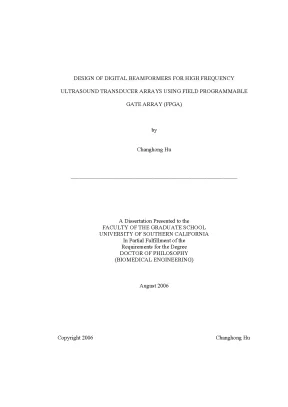
Tải xuống để đọc toàn bộDESIGN OF DIGITAL BEAMFORMERS FOR HIGH FREQUENCY ULTRASOUND TRANSDUCER ARRAYS USING FIELD PROGRAMMABLE GATE ARRAY (FPGA) by Changhong Hu ___________________________________________________________ A Dissertation Presented to the FACULTY OF THE GRADUATE SCHOOL UNIVERSITY OF SOUTHERN CALIFORNIA In Partial Fulfillment of the Requirements for the Degree DOCTOR OF PHILOSOPHY (BIOMEDICAL ENGINEERING) August 2006 Copyright 2006 Changhong Hu UMI Number: 3238308 Copyright 2006 by Hu, Changhong All rights reserved. UMI Microform 3238308 Copyright 2007 by ProQuest Information and Learning Company. All rights reserved. This microform edition is protected against unauthorized copying under Title 17, United States Code.
ProQuest Information and Learning Company 300 North Zeeb Road P. Box 1346 Ann Arbor, MI 48106-1346 ii ACKNOWLEDGEMENTS This thesis is the result of several years of hard work whereby I have been accompanied and supported by many people. It is a pleasant aspect that I have now the opportunity to express my gratitude for all of them. I would fist like to thank my advisor, Professor K.
Kirk Shung who gave me the opportunity to work in the NIH Ultrasonic Transducer Resource Center at University of Southern California (USC). I am deeply grateful for his helping, stimulating and encouraging me in all the time of research. I wish to express my warm and sincere thanks for my thesis committee: K. Kirk Shung, Jonathan Cannata, Jesse Yen and E.
Kim for helping me on the preparation of this dissertation. I would also like to thank the faculty, staff and my colleagues, especially Peijie Cao, Qifa Zhou, Ruibin Liu, Kevin Snook, Xiaochen Xu, Jin Ho Chang, Jay Williams and Joe Han for their assistance with this work. I owe my loving thanks to my wife Xuemei Deng, my daughter Ziyan Hu. They give me many supports.
Without their encouragement and understanding it would have been impossible for me to finish this work. My special gratitude is due to my parents, my brother, my sisters and their families for their loving support. iii TABLE OF CONTENTS ACKNOWLEDGEMENTS ii LIST OF TABLES vi LIST OF FIGURES vii ABSTRACT xii Chapter 1: HIGH-FREQUENCY ULTRASONIC IMAGING AND HIGH-SPEED ELECTRONIS 1 1.2 HIGH FREQUENCY ULTRASOUND IMAGING: SINGLE ELEMENT 5 1.3 HIGH FREQUENCY ULTRASOUND IMAGING: ARRAYS 8 1.4 HIGH SPEED ELECTRONICS 14 1.5 THESIS OUTLINE 18 Chapter 2: BEAMFORMING PRINCIPLE 19 2.2 DIGITAL BEAMFORMING METHODS 23 2.1 DIRECT DELAY-SUM BEAMFORMING 23 2.3 BANDPASS TIME-DOMAIN BEAMFORMING 26 2.4 FRACTIONAL-DELAY INTERPOLATION BEAMFORMING 27 2.5 FREQUENCY DOMAIN BEAMFORMING 31 2.3 DELAY CALCULATION 31 Chapter 3: DIGITAL BEAMFORMING IMPLEMENTATION 34 3.1 FIELD PROGRAMMABLE GATE ARRAY (FPGA) SELECTION 34 3.2 FPGA STRUCTURE OVERVIEW 35 3.4 SIMULATION RESULTS 44 iv Chapter 4: DEVELOPMENT OF A HIGH FREQUENCY ULTRASOUND DIGITAL BEAMFORMER WITH ANUULAR ARRAY TRANSDUCERS 47 4.2 FABRICATION AND EVALUATION OF THE TRANSDUCER 49 4.1 ANALOG FRONT-END CIRCUIT AND TRANSMIT BEAMFORMER 57 4.2 DIGITAL BEAMFORMER CIRCUIT 59 4.5 DISCUSSION AND CONCLUSIONS 62 Chapter 5: DEVELOPMENT OF A HIGH FREQUENCY ULTRASOUND DIGITAL BEAMFORMER WITH LINEAR ARRAY TRANSDUCERS 67 5.2 LINEAR ARRAY FABRICATION AND DESIGN CONSIDERATIONS 71 5.1 ANALOG FRONT CIRCUIT AND TRANSMIT BEAMFORMER 84 5.2 DIGITAL BEAMFORMING CIRCUIT 89 5.3 GRAPHIC USER INTERFACE 93 5.5 DISCUSSION AND SUMMARY 94 Chapter 6: SUMMARY AND FUTURE WORK 100 6.2 FUTURE WORK 102 BIBLIOGRAPHY 112 APPENDICES 122 APPENDIX A 122 v APPENDIX B 126 APPENDIX C 130 vi LIST OF TABLES Table 5.1: Parameters of the Linear Array Used in this Study 72 Table 5.2: Comparison of the –6 dB lateral beam width and the depth of focus with variable active elements for linear array (30 MHz) between simulation and theoretical calculation 78 Table 5.3: Comparison of the –6 dB lateral beam width and the depth of focus with variable active elements for linear array (35MHz) between simulation and theoretical calculation 79 Table 6.1: Number of control signals require for current design 108 Table 6.2: Number of control signals require for new design 108 vii LIST OF FIGURES Figure. Geometry of an ultrasound transducer.
D is the focal 3 distance, A is the diameter, and DOF is the depth of focus Figure. The general diagram of UBM system developed (Chen 2000). Diagram of the linear array (Top) and phased array (Bottom) 10 Figure. Electronic scanning with a linear array.
The subgroup is first selected, fired to form one line in an image, and the same 12 pattern is then repeated for the set of subgroup along the array, in a sequential and repetitive way Figure. If the elements are triggered imultaneously (Top), the formed beam patter is wider that 13 that formed by triggering outer element first and center element late (Bottom) Figure. The diagram of the PCB trace impedance calculation. W is the 18 trace width, t is trace thickness, and h is the layer thickness Figure.
The beamforming process 20 Figure. Diagram of the zero-padding beamforming 25 Figure. Simulation using the zero-padding algorithm. (A) An echo sampled at 1 GHz.
(B) The same echo sampled at 100 MHz. (C) 25 Zero-padding the echo in B by a factor of 10. (D) Low-pass filtered echo from C Figure. Illustration of the band-pass procedure 27 Figure.
Comparison of the ideal waveforms and the outputs from FD 30 filters using Lagrange filter Figure. Diagram of the beamformer in frequency domain 32 Figure. Phase delay before and after the beamforming 33 viii Figure. Delay calculation diagram 33 Figure.
The input/output block (IOBs) of Virtex-E FPGAs 37 Figure. Detailed structure of CLBs of Virtex-E slice 38 Figure. Delay implementation for one channel, D is the course delay 39 coefficient and d is the fine delay coefficient Figure. Coarse delay structure, cock delay is decided by the 40 sampling rate Figure.
Fine delay structure 41 Figure. The diagram of the finite element machine used in dynamic focusing procedure, each circle presents the state when the time 43 coefficient is popped out Figure. The logic structure of the implemented beamformer, it 44 includes dynamic receiving focus and sum logic Figure. Simulation result of two-channel with dynamic focusing 45 Figure.
First zoom part of Figure 3. Second zoom part of Figure 3. The simulation beam pattern (8X2 mm) of focused annular array transducer in lateral-depth (XZ) plane. The 6 element 53 annular array has 3 mm diameter with 30 µm kerfs size Figure.
The measured beam pattern (8X2 mm) of focused annular array transducer (3 mm diameter, 30 µm kerfs size) in lateral- 54 depth (XZ) plane Figure. The measured cross-section view (2X2 mm) of the beam at focal point, where x, y are the two lateral directions 55 ix Figure. Block diagram of the imaging system. The imaging system consists of a transducer, a six-channel transceiver, an FPGA 57 based beamformer, a DSP microprocessor-based scan converter and a PC computer for displaying the image Figure.
The photograph of the assembled transceiver and beamformer 60 board Figure.6 Wire phantom (20 µm Tungsten) images. The ex vivo corneal images of an excised rabbit eye using the 64 annular array Figure.8 The comparison of lateral intensity profile of measurement (solid line) and simulation (dot line) along the focal point (6. The 66 –6dB width is 150 µm, 200 µm for simulation and measurement, respectively Figure. The –6 dB contour of simulation beam pattern (Top) and lateral intensity profile at focal point (Bottom) of linear array transducer 76 (30 MHz, 100 µm pitch size) in lateral-depth (XZ) plane with different active elements Figure.
The –6 dB contour of simulation beam pattern (Top) and lateral intensity profile at focal point (Bottom) of linear array transducer 77 (35 MHz, 50 µm pitch size) in lateral-depth (XZ) plane with different active elements Figure. The comparison of the –6 dB contour of simulation beam pattern 80 using apodization functions Figure. The comparison of lateral intensity profile using apodization 81 functions at focal point Figure. The comparison of –6 dB width using different apodization 81 functions x Figure.
Block diagram of the overall imaging system 83 Figure. Excitation pulse and its spectrum 85 Figure. Schematic of the 4th Butterworth filter 86 Figure. Spectrum of the filter (solid line) and the spectrum of the signal 87 (dot line).
Block diagram of the crosspoint switch 89 Figure. The flow chart of the firmwork developed for FX2 96 Figure. The flow chart of the data acquisition software 97 Figure. Excised rabbit eyeball image from 30 MHz linear array with the pitch size of 100 µm (A) and the 35 MHz, 64 element 99 linear array with the pitch size of 50 µm (B) Figure.
Spectrums of the negative spike and bipolar pulser 103 Figure. Snapshot of the bipolar pulser 104 Figure. The peak-to-peak value of echo from quartz target using one element from the 35 MHz, 64 elements linear array transducer 106 with variable peak-to-peak value of the monocycle Figure. Schematic of proposed 64-channel digital beamformer 110 Figure.
Assembly high-speed connector and cable form Samtec 111 Figure. Layout of digital control board. Layout of analog front board. Layout of digital beamformer board.
Layout of the amplification and cross-switch board. Layout of digital contrl board. Layout of digital beamformer board. 129 xii ABSTRACT Ultrasound imaging is a well-established and widely used clinical technique that shows the cross-sectional image of human tissues.
Conventional ultrasound systems are targeted at imaging the heart or abdominal organs and the spatial resolution at this frequency range is on the order of a few millimeter. An ultrasound system will be capable of providing a better spatial resolution if higher frequencies are used. High frequency ultrasonic imaging (> 20 MHz) using single element transducers has been shown to be clinically useful in ophthalmology, dermatology, small animal and intravascular imaging. In recent years, more studies have been carried out on the development of high frequency array transducers.
Due to the fact that beamforming electronics is not yet commercially available for the high frequency arrays, prototypical digital beamformers for the annular and linear arrays were specifically developed for the purpose of testing the annular array and linear array developed at the NIH Transducer Resource Center at University of Southern California (USC). Field Programmable Gate Arrays (FPGAs) have been demonstrated to be an ideal platform for beamformer development. They provide the processing speed necessary for real-time beamformer with high frequency array transducers. Two digital beamformers were developed for the 8- element annular array and 64-element linear arrays.
xiii An imaging system composed of an annular array transducer, an eight- channel analog front-end, a field programmable gate array (FPGA) based beamformer, and a DSP microprocessor based scan converter was deveolped. A PC computer is used as the interface for image display. The beamformer that applies delays to the echoes for each channel is implemented with the strategy of combining the coarse and fine delays. The coarse delays that are integer multiples of the clock periods are achieved by using a First-In-First-Out (FIFO) structure and the fine delays are obtained with a Fractional Delay (FD) filter.
Using this principle, dynamic receive focusing is achieved. The image from a wire phantom obtained with the imaging system was compared to that from a single element transducer using one channel of the system. The improved lateral resolution and depth of field from the wire phantom image were observed. Images from an excised rabbit eye sample were also obtained, and fine anatomical structures were discerned.
A real-time digital beamformer for high frequency (>20 MHz) linear ultrasonic arrays was designed and developed. The system can handle up to 64- element linear array transducers and excite 16 channels and receive simultaneously at 100 MHz sampling frequency with 8-bit precision. Using fractional delay filters, fine delays as small as 1ns can be implemented. A frame rate of 30 frames per second was achieved.
Wire phantom (20 µm tungsten) images were xiv obtained and –6 dB axial and lateral widths were measured.
Nội dung được bảo vệ bản quyền — Tải xuống đầy đủ
Trích dẫn luận án này
Changhong Hu (2006). Thiết kế beamformer kỹ thuật số cho mảng transducer siêu âm tần cao [Luận án tiến sĩ, University of Southern California]. LuanAn.net. https://luanan.net/ky-thuat-dien-dien-tu/ky-thuat-dien-tu/thiet-ke-beamformer-ky-thuat-so-transducer-sieu-am-fpga
Từ khóa và chủ đề nghiên cứu
Từ khóa liên quan
Xem thêm luận án cùng lĩnh vực
Chủ đề nghiên cứu
Câu hỏi thường gặp
Luận án "Thiết kế beamformer kỹ thuật số cho mảng transducer siêu âm tần cao" nghiên cứu về vấn đề gì?
Luận án tiến sĩ thiết kế beamformer kỹ thuật số cho mảng transducer siêu âm tần cao FPGA. Nghiên cứu xử lý tín hiệu số và beamforming trong hình ảnh y khoa.
Luận án "Thiết kế beamformer kỹ thuật số cho mảng transducer siêu âm tần cao" được bảo vệ tại trường nào?
Luận án này được bảo vệ tại University of Southern California. Năm bảo vệ: 2006.
Luận án "Thiết kế beamformer kỹ thuật số cho mảng transducer siêu âm tần cao" thuộc chuyên ngành gì?
Luận án "Thiết kế beamformer kỹ thuật số cho mảng transducer siêu âm tần cao" thuộc chuyên ngành Biomedical Engineering. Danh mục: Kỹ Thuật Điện Tử.
Luận án "Thiết kế beamformer kỹ thuật số cho mảng transducer siêu âm tần cao" có bao nhiêu trang?
Luận án "Thiết kế beamformer kỹ thuật số cho mảng transducer siêu âm tần cao" có 148 trang. Bạn có thể xem trước một phần tài liệu ngay trên trang web trước khi tải về.
Cách tải luận án "Thiết kế beamformer kỹ thuật số cho mảng transducer siêu âm tần cao" về máy như thế nào?
Để tải luận án về máy, bạn nhấn nút "Tải xuống ngay" trên trang này, sau đó hoàn tất thanh toán phí lưu trữ. File sẽ được tải xuống ngay sau khi thanh toán thành công. Hỗ trợ qua Zalo: 0559 297 239.